This is a simple calculator using the Carnot efficiency equation. It uses the refrigerant temperatures to estimate the approximate COP. The actual real-life COP is usually about 50% of the theoretical Carnot COP. (see further info at the bottom). Note – This is only an estimate for one point in time. Various things affect the actual daily or annual result. SPF or SCOP should be used to assess expected annual averages. [Fahrenheit version]
The Refrigerant condensing temperature is likely to be a few degrees (C) hotter than the water flow temperature.. maybe 2° to 4° (C) warmer. The evaporating temperature might be 5° to 8° (C) colder than the outside air temperature.
The two ‘offset’ values at the bottom are approximate estimates to correct for the above temperature differences.
In general, these offsets will be lower at minimum compressor speed and greater at maximum speed. flow-return dt of about 5 degrees is assumed.
Carnot COP = TH / ( TH-TL ) Using absolute temperatures, where TH = condensing (hot) temperature and TL = evaporating (low) temperature. The actual COP is about 50% of the Carnot COP
Be mindful that the COP result is for any one moment. Below 5 or 7°C there can be defrosts, and this will reduce the COP. This could be very variable, but often somewhere in the region of up to 10% during periods where defrosts happen. I have also added the option to add a percentage to allow for the power used by fans and pumps.
Uses for the comparator
It can be good for making comparisons… e.g. to see the likely percentage improvement in COP if you increase the radiator size, or to estimate the reduction in COP due to a poorly ventilated ASHP (where air is several degrees colder due to re-circulation). It can help extrapolate COP readings from data sheets (e.g. often given at 35°C).
Please be cautious if changing dt values (see bottom).
You can change the Carnot Efficiency from 50% to help align estimated to your values, then stick with this percentage whilst varying temperatures.
Be mindful that there are many factors that contribute to the actual resulting COP over the day.
Other calculators
The below is an attempt at ‘spelling out’ the dt issue.
‘A’ is a standard condition with flow-return dt of 5. If we now consider ‘B’ with dt of 10, the flow-rate must have halved to achieve this (assume kW heat is the same). The radiators etc have less flow-rate, so whilst the condensing pressure is lower (better COP), the heat is delivered to the radiators at a lower mean temperature (see graph). To get a ‘level playing field’ (as C) we have adjusted the flow temperature up so that the average flow-return is about the same. This raises the refrigerant temperature The most energy-efficient option here is A.
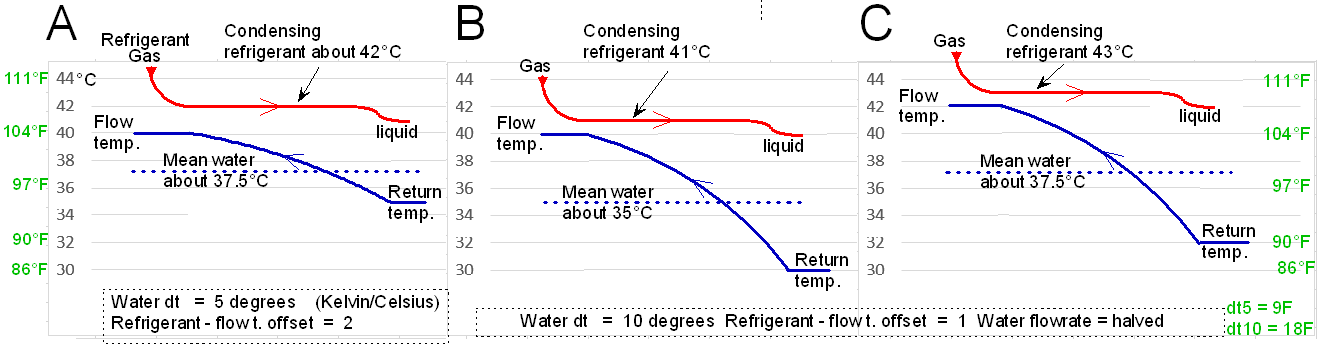
Note, the condensing temperature is guessed from my experience taking readings from heat pumps. Also, the ‘flat’ condensing line is not quite flat due to pressure drops. CO2 heat pumps are quite different, there is no actual condensing temperature with them.
Also note that the heat transfer within the heat-exchanger is dependent on the temperature difference between the red and blue lines. For ‘B’ and ‘C’. There is a very big variation across the heat exchanger, so the full area of heat exchange is not evenly spread, so not so well utilised.
Note: We often cite 5 degrees (or 9F) as the normal dt for heat pumps. However, the actual water temperature has a bearing on this. e.g. on a highly efficient system operaing at a nice low flow temperature of 30C (86F), then the dt could be only 3 or 4 degrees (5-7F). However, if a system is operating at say 50C (122F) degrees could have a dt of 6 or 7 (10-12F). The precentage difference between the room and water temperature should be considered when deciding on a suitable dt.
Should we exclude dhw production from COP figures, but include dhw production in SPF?