In the past, hot water was only a small percentage of a building’s total energy demand (e.g. 20%). However, as the insulation levels of buildings increase, and the space-heating demand drops, the proportion of heat directed to DHW increases. Furthermore, our hot water use for washing and showering has if anything increased – we are all cleaner! So, half of the total heat requirements can in some cases be for domestic hot water.
Low temperature emitter systems (e.g. underfloor heating) can make room heating with heat pumps very efficient, but with hot water, there is little opportunity to reduce the working temperatures, and it can be quite a challenge to achieve the highest energy-inefficiencies (COP) during hot water production when using a heat pump. That said, it should be several times better than an electric immersion heater. In very general terms, where room heating (space heating) might have a COP of 3.5, When heating a hot water cylinder, the COP may be only 2.5 in winter. However, never forget that an immersion heater has a COP of only 1, so a heat pump should always be better than an electric heater.
Combi gas boilers heat water on-demand, but heat pumps always need a storage cylinder. There are two main types of hot water storage cylinders.
1. The conventional hot water cylinder.
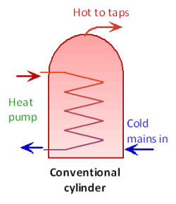 This has a heat-exchanger coil to transfer heat from the heat pump. The cylinder holds the actual water that comes out of the taps. Traditionally in the UK, these were fed from open-topped header tanks in the loft, and referred to as ‘vented’. This method has several drawbacks, namely: contamination of the water in the loft tank, risk of freezing in the loft, and low water pressures for showers.
We have aligned with most other countries and now, almost all modern cylinders are ‘un-vented’. these are fed directly with mains water, after the required pressure regulators. This system usually gives better water pressure for showers etc., and can be used with smaller-bore, more energy-efficient distribution pipework.
The heat-exchanger coil within the cylinder needs to be far bigger than that designed for a boiler. Ideally with only a 5°difference (9F) difference between the heated water from the heat pump and the water available to the taps. This is achievable if a suitably large coil is used. I have found 3m² of coil surface area to be most efficient and practical for small domestic heat pumps.
2. The ‘Thermal Store’ type cylinder
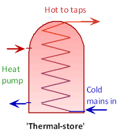 This is the traditional method used in Sweden amongst other countries. With this system the cylinder water circulates directly to the heat pump. A large heat-exchanger coil inside the cylinder takes cold mains water, and heats it up instantaneously as it passes through. This system has advantages and disadvantages.
Advantages
* Legionella risk is minimal due to low water content within the heat-exchanger coil. Legionella regulations may not apply.
* The hot water can be produced at high pressure (same as cold-tap pressure), so distribution pipes can be of smaller bore, and flow rates high.
Disadvantages
* The water temperature at the tap will be flow-rate dependant – the faster the flow, the cooler the water.
* Storage temperatures may need to be kept higher than the conventional system – not ideal for heat pumps.
* The cylinder temperature tends to drop uniformly over its height, so may need topping up more frequently.
The conventional cylinder is a bit easier to configure and has advantages of stratification – incoming cold water stays at the bottom as hot water is drawn off the top. The thermal store may often have inferior performance unless designed well. However, developments may improve these finer details, so I should keep an open mind on them. (see HeatGeek Super Cylinder)
A system akin to the thermal store is the method using an external plate heat-exchanger. This is becoming more popular, as used by Ecodan. Maybe in-part because it’s easier to manufacture.
Pre-heating
In the past, there were maximum temperature limits for heat pumps, and many needed an electric element in order to achieve the last 5 or so degrees. This has improved over time as refrigerant types change. Many heat pumps will achieve higher temperatures, eliminating the need for an immersion heater. However, some still use an immersion heater for a periodic ‘parsturisation’ to prevent any legionella bacteria.
Batch heating
To improve energy efficiency, it is important to keep the water temperature within the heat pump to the lowest values possible. However, most cylinders are maintained at over 50°C all the time, and often heated to 60°C weekly for legionella protection (often with assistance of a direct electric immersion element).
If the cylinder storage is large-enough, then a considerable delay can be arranged before the heating is re-triggered, by which time the bottom half of the cylinder is likely to become cold as water is used, and hot water is displaced. The heat pump can then heat the lower section from this cooler temperature right up to the required hot temperature. The average water temperature that the heat pump ‘sees’ is therefore considerably lower, and the energy efficiency is significantly improved. Adjusting the position (height) of the control sensor probe can help to achieve this. If it is raised up the cylinder, there will be more delay before the cylinder starts re-heating. Careful use of a time clock could also assist here by making the bottom of the cylinder colder at certain times. However, the total volume of available hot water will be reduced at times. This may not be a problem for much of the time. It’s a matter of balancing the need to save energy and the risk of running out of hot water. This varies greatly from one user to another.
For a heat pump unit with an integral cylinder, it is possible to utilise the hot discharge pipe from the compressor. This ‘de-superheater’ can provide a small amount of hot water whilst either room heating or cooling. There are various methods that manufacturers can use to optimise the DHW heating. Some improve the energy-efficiency, some reduce the manufacturing costs of the unit.
Heat pump manufacturers do not like increased production costs. Indeed, they want their products to be competitive. Optimisation options like this may not always be embraced, and there is not enough drive at present to improve the energy-efficiency of systems. that said… with the recent growth in the industry, maybe we will soon see improvements
Saving energy and water in the distribution pipes
Also read the AECB Water Standard
Whatever your method of producing hot water for baths, sinks and showers, you should make sure that energy and water is not wasted due to a long pipe-run from the storage cylinder to the tap. Whenever a hot tap is first turned on, there is a time-delay before water comes through at a useable temperature.
Firstly, this is a waste of water.
Secondly, it is a waste of heat since the hot water within the pipe will slowly cool after the tap was last used and heat will be lost. Sometimes this heat is useful to the building. Nonetheless, these losses are generally undesirable. One solution to save water is to use a pumped-loop (secondary pumped return) around the building so that hot water is always close to the tap outlets. This system is common in hotels, and will save water and reduce waiting time, but it could waste a lot of heat. Ideally the system would be designed so pumped loops are not needed. This may involve positioning the cylinder centrally, and making pipe runs as direct as possible. Don’t assume that your installer will necessarily do this.
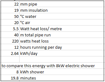
It’s ALWAYS worth doing a few sums so as to understand the quantities. Given that an insulated hot pipe can lose say 5.5watts per metre pipe run, and a pumped return could have 40m of pipe (flow plus return). This could total 220watts, or, if circulating for 12hrs per day, could total 2.6kWh/day. This is equivalent to the energy used for one 20minute shower. This illustrates how wasteful secondary pumped loops can be.
Good housekeeping
In the days of cheap energy and before energy was seen as a problem, the pipe runs from cylinders were made nice and large, usually reducing in diameter as they got to the last tap. If your washbasin was at the end of a long run, then it will take ages for the hot water to come through.
To minimise these losses there are a few things that can be done.
- Use the smallest size pipe possible to maintain an acceptable flow rate.
- Use multiple pipe-runs from the cylinder so that each pipe is smaller (e.g. a separate pipe to the bath & separate small-bore to basins).
- Insulate pipes that go to frequently used taps. Definitely insulate a pumped-loop system.
Experiment
1. First thing in the morning (following no tap use for many hours), put a bowl in your kitchen sink and turn on the hot tap and see how long it takes before the water is a useable hot temperature. This amount of water is wasted frequently. This quantity of hot water is left cooling in your pipe work.
2. Assess the flow rate. How quickly can the sink be filled? Is it quicker than needed? If so, you should be able to improve matters.
Repeat this experiment for all your sinks.
Possible solutions
Reduce the pipe diameter from your cylinder.
Make the pipe route more direct, hence shorter. It is amazing how tortuously long some pipe routes can be.
Fit a small-bore pipe direct from the cylinder to that distant wash basin. Plastic pipe has a considerably smaller bore then the equivalent size in copper.
Insulate frequently-used pipe runs. Noise could increase when smaller pipes are used in a system with very high pressure, but I have never found this to be a problem.
Pipe sizes and flow rates. (also see simulator)
The following chart gives the internal volume of common plastic and copper pipes. Dimensions may vary slightly with different manufacturers . However, it shows the dramatic difference in internal size between copper and plastic pipes. The following chart might be useful for assessing the size of pipe that you may be able to reduce to.
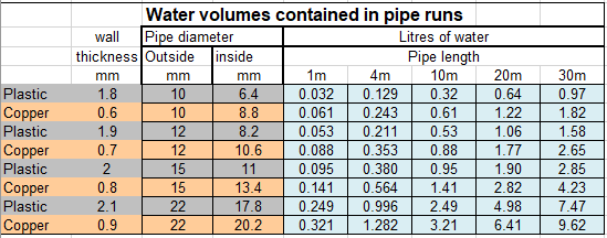
Note, this chart can only be used as a rough guide. It is interesting to note how dramatic the effects of the internal diameter is on the flow rate. The internal bore of plastic being much smaller than that of copper, this may be an advantage, or a disadvantage depending on your requirements.
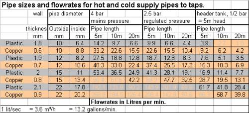
Notes
The pressures given are just a guide. The height difference from loft header tank to the tap causes the pressure, these systems need the biggest pipes. Mains pressure systems (e.g. thermal store) can give the highest tap pressures, so pipe sizes can be smaller. That said, mains pressure can vary considerably.
All information given here in good faith. No responsibility can be taken by use of these figures.
If you are considering pipe sizes and pressure-drops, you can have a play with this great little on-line calculator http://www.pressure-drop.com/Online-Calculator/
John Hearfield’s page is great
You can also read my blog about the simple basics of pressure drops, flow-rates and pipe length. and Distributing hot water to tap outlets
Use this to work out how quickly a cylinder will heat up. This can also apply to a buffer cylinder