LENGTH is just as important as pipe diameter
Try this flow-rate and pressure-drop simulator
[ Note- a simpler blog on this topic is here ]
It is very important to choose the correct diameter pipe for any pipe run. Unfortunately, pipe sized are sometimes guessed. If the pipe is the wrong diameter, then problems may result.
If a certain flow rate of water is required in a pipe, then we need a circulation pump (circulator) to create a pressure to ‘push’ the water through the pipe. In every section (foot or metre) of pipe, there will be a pressure drop when water is flowing. In brief – the bigger the pipe diameter, and/or the shorter the pipe is, the easier it will flow, and the less energy needed for the circulator pump.
If the pipe run is relatively short, the pipe runs are often the same diameter to that of the fitting size on the heat pump. If however the pipe runs are long, the pipe run diameter may need to be larger than the connection size so that the total pressure drop is within the limits of the circulation pump.
Pressure is quoted in many units. 1bar = 1 Atmosphere = 14.5 psi (lb/sq. inch)
1 bar = 10m head of water = about 33ft of water = 100kPa (kilo pascals)
Most domestic circulators (central heating pumps) can produce a maximum of 5 or 6 m head of water. i.e. they could just manage to raise water 5 or 6 metres. That said, the more optimal pressure to operate at for low power consumption, might be between 2 or 3 m heat of water (0.2 to 0.3 bar).
What flow rate do I need?
There is one useful simple formula that gives you the relationship between Flow-rate, heat (Kw) and temperature rise (or drop) (delta t, Δt, dt,)
Heat (kWatts) = Flowrate (Litres/sec.) x 4.2 (Specific heat of water) x temperature rise (Δt or dt).
To rearrange things
Flowrate (lit/sec.) = Heat (kW) / 4.2 / temperature rise
If we have radiators that are expected to give out 5 kW of heat (at our water design temperatures), and we expect the water to drop by 5 degrees (9°F) from inlet to outlet, we can calculate the required flow by using the following;
Lit/sec = 5kW / 4.2 / 5º = 0.24 lit/sec. = 14.3 litres/ min
So, now we know the required flowrate, we can estimate pipe sizes.
Examples of pipe run sizing where a long run is larger in diameter than the diameter of the connections at the ends.
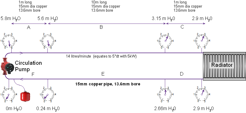
Firstly, lets consider this example with pipe runs of all 15mm copper. I have put pressure gauges on the pipe (to show relative pressures). The pressure is highest at the outlet of the pump and lowest at the pump’s inlet. The pressure drops as the liquid flows around the circuit. (the pressure is quoted in ‘m H20’ ).

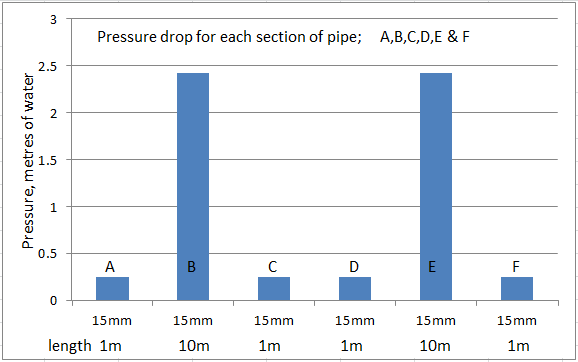
As we can see from this diagram, the pressure drop of the short 1m long sections (a,c,d & F) are relatively small. However, the two 10m long pipes make the total pressure required almost 6m head. This is beyond the capability of most circulating pumps.

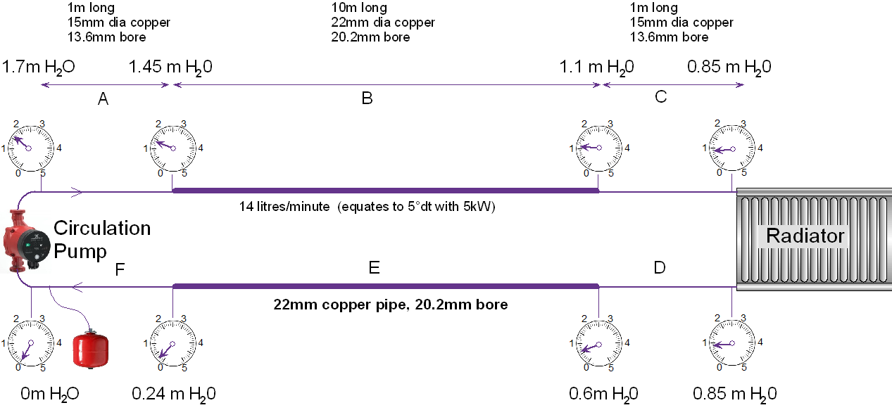
Now let us consider increasing the 10m long middle sections of pipe from 15mm copper to 22mm copper.


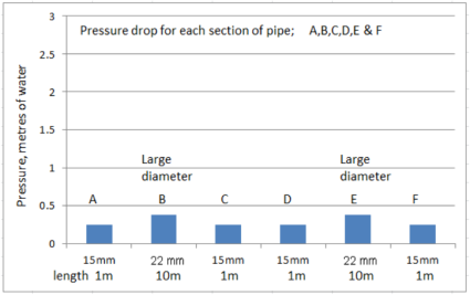
As we can now see, the two long sections now have reasonable pressure drops such that the total pressure drops (by adding all the pressure drops together) is now down to under 2m head of water. This is a nice energy-efficient low pressure to work with. If we were to re-calculate with larger pipe also at the 1m ends, we find that the total pressure that the pump ‘sees’ hardly changes, so there is little advantage to this.
Note, every fitting and valve also adds a pressure drop. This can be calculated. However, it is sometimes easier (and good enough) to increase the theoretical pipe run length to allow for valves and fittings.
It is also important to realise that for the same common pipe size (e.g. 15,22 or 28mm) the internal bore of plastic pipe is considerably smaller than that of copper. It also make a surprising difference to the pressure drops. In our example, we have a total pressure drop of almost 6 m head of water. If we were to use plastic pipe instead, the pressure required would be over 12 m head of water. There is nothing wrong with plastic pipe, it is a matter of choosing the correct bore diameter for the job.
This useful online calculator can be used to estimate pipe sizes http://www.pressure-drop.com/Online-Calculator/
Why do electricians find this topic easier?
The same principle applies to electrical wires as it does to water pipes.
The voltage-difference from one end of a cable to the other is the same as the pressure-difference from one end of a pipe-run to the other.
The current (amps) is the same as the flow-rate (litres/sec.) .
An electrician can measure the voltage and current very easily and accurately at any point. A heating engineer has no such luxury; the pressure and flow-rates at various points on the pipework are normally impossible to measure, so its hard to really know what is going on.
For an electrician, it is easy to understand as illustrated by the following example of the power connection to a garden shed at the end of a big garden. The relatively short cable from house fuse box to a junction box outside the house need to be say 2.5sq.mm (cable size). Let’s say the volt drop is 2.3volts which is only 1% loss (230v – 2.3v = 227.7 volts = 1% loss); perfectly acceptable.
If we now factor in the very long cable run along the garden to the shed, we find that the cable may need to be as large as 16sq.mm to achieve a similar volt drop over the long length. We would be losing a further 1% here ( down to 225v now). Again, this is acceptable.
In this example, The long garden run must be 16 sqmm, but there would be little advantage by increasing the size of the small short cable at the end.
The bottle-neck principle does not apply here in the same was as it would to traffic on a motorway. If cars acted like water molecules or electrons, they would ‘push’ bumper to bumper and shoot through a bottle-neck at extremely high speed!
If you are still reading… this seems interesting https://www.youtube.com/watch?v=F4VM_Xlp-SU&t=225s
This calculator could be handy too