[Note, this blog was published 2014.. the underfloor heating industry has developed a lot in the last 5 years]
Many years ago, when heat pumps were not so common, I found it a real struggle to get any of the main underfloor heating suppliers to embrace the need for low water temperatures for use with heat pumps.
15 years on, and I’m sure that things have changed dramatically, but I’m still stumbling across things that make me doubt that.
When I visited Germany over 10 years ago, I got the feeling they commonly use much closer spacing between floor pipes than we do in the UK, and I have read of very close spacing (50mm) in Austria. I realise these are potentially cold countries, but even recently visiting a Spanish heat pump company, they were surprised that we don’t use closer pipe spacing (more pipes).
Over the last 6 months I have heard several references in the trade to; ‘never use closer than 150mm pipe spacing’. However, CIBSE clearly give ratings for 100mm spacing, as does the MCS Emitter Guide, so why are some in the UK so resistant to putting more pipe into floors.
To basics – COP v heat pump water temperature
Heat pumps are more energy-efficient if the water temperature is low.
Coefficient of performance (COP) = heat output / electrical power input
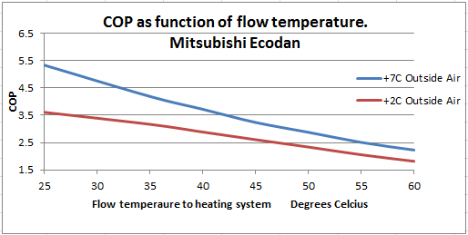
This graph of an air source heat pump shows how beneficial a low flow temperature is. Units like this with electronic expansion valves are particularly efficient at very low water temperatures.
How to get a low flow temperature with underfloor heating
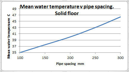
The values for the example graph above have been extracted from CIBSE, and show a general trend for a fixed heat output. It demonstrates what we all should know – the closer the spacing, the lower the required water temperature for the same heat output.
Putting the two together we could plot pipe spacing v COP. It would clearly indicate that closer spacing improves COP, so why do some seem reticent to embrace close spacing? Is that added cost for more pipe really that much??
I have gleaned that some people have the notion that close spacing could lead to warm floors and an overly hot house. The whole point here is that with closer spacing, we can turn the water temperature setting (heating curve) down, and get the same heat output, thus improving the COP.
I think some of the fears about hot floors stem from boiler systems, many of which had plenty of extra output capacity for quick warm-up, and hot patches could result. However, heat pumps are generally slower response, with lower water temperatures, so are much more forgiving in this respect. I recently visited a system where I had used 50mm spacing in an always-open loop in a bathroom. I asked the owner if they had ever thought the bathroom floor was too warm. The answer was no, never.
The reason why I had used 50mm spacing was that we didn’t want a buffer cylinder, so I was trying to ensure there was adequate water quantity, and flow-rate in the floor – effectively using the floor as a buffer.
Another hot (excuse the pun) topic here is floor coverings. People are now seeing that a carpet will drop the star rating for RHI, so there is an added financial incentive for having solid (tiled etc.) floor, as seems far more common in Germany, instead of carpet.
However, by designing a house where some rooms are tiled, and some are carpet, you are somewhat limiting any changes that future occupants might wish. (e.g. if 100mm spacing in a carpeted room, and 200mm in a tiled room). Underfloor pipes are literally set in stone, so can never be changed. The only solution that I could think of here would be to interlace the loops (given that there is often more than 1 loop per room). There is always the option of turning off one of the interlaced loops. I like multiple interlaced loops.
I have come across an installation where a new owner had fitted thick pile carpet in one room without thinking the affect it would have. The result was a cold room, remedied only by turning up the water temperature, thus increasing the running cost, and the reliance on room thermostats to limit heat to the tiled rooms.
The general design approach for underfloor is to consider the heat required (e.g. watts/sq m) , but unless a buffer cylinder is fitted, we should also consider what heat is being delivered to the floor, given that some zones will be closed for some of the time, and the outside temperature is seldom at design temperature (-2C etc.). For most of the time, we have far more available heat than the floor needs. Even with modulating heat pumps, there can still be a tendency for the flow temperature to stray above the theoretical flow/return temperatures. This is another reason for favouring more pipe in the floor. Furthermore, MCS requires the heat pump to provide at least 100% of the design at -2C etc. Due to models only being available in certain size jumps, the heat pump installed is often oversized, so this is an added reason for ensuring that there is adequate pipe in the floor.
For any thinking that buffer cylinders are the perfect answer – they may be an answer, but they are seldom perfect, as shown by this piece of monitoring. (openenergymonitor.org)
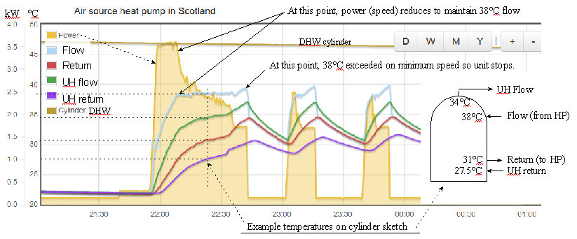
In this example of a system with a simple buffer tank, the heat pump flow/return needs to be approx. 4 degrees hotter than UH flow/return. This could reduce energy efficiency by 10%, plus the added energy to run a second circulation pump.
A buffer can usually be avoided IF enough zones are always on AND if there is plenty of pipe in the screed.
Another potential worry is the thermal mass of the screed. I was recently involved in the design of a passive house where a buffer cylinder was not wanted, so I proposed to use the screed as the buffer, and fitted 9 x 100m loops with average 100mm spacing in a floor that was 200mm thick. One might expect some temperature overshoot, and I may not have been so bold as to propose it if it were not for the fact that due to the interlaced nature of pipework, we could shut off ½ the zones if we needed to.
The result was surprisingly good with all room zones open and control on one master thermostat. The whole house has very even temperatures. This demonstrates the self-regulating nature of very low temperature underfloor heating.
Another concern I have heard of is the pumping power required for such a lot of pipe. In the above passive house example. If the heat pump needs 10 lit/min to give a 5 degree flow-return dt , then the flow rate is about 1.11 litres/min for each pipe loop. If we used a more standard 5 loops, the flow rate per loop would be 2 litres/ min. For the same heat (kW) and same dt, more pipe actually means less pumping power since the heat output per m of pipe is lower, and the flow-rate for each loop is lower.
Finally, I have also come across the notion that mixer valves and pumps are desirable, even for a heat pump. Generally, mixing valves hinder energy-efficiency. Here is an example to illustrate the potential penalty of having a mixer even if the mixer never actually mixes (i.e. its fully open).
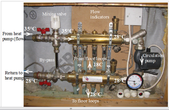
The arrangement here with recorded temperatures shows that the flow to the floor is always equal in temperature to the return to the heat pump. In this example, the flow from the heat pump is 7 degrees higher than the flow to the floor. The mean floor temperature was only 23°C (average of 28 & 18).
If the mixing valve and pump were removed, the heat pump’s flow could go directly to the bottom manifold.
To get the same floor heat output, the heat pump setting could be adjusted down so as to give a working flow of 26 and return of 20. This is a reduction in flow temperature of 9 degrees, potentially (according to our first graph at top of page ) saving 13%.
(see top graph – The COP at 35°C is 3.1, at 26C its 3.1, saving 13% in COP).
All these little details can eat into potential savings. They should be dealt with at design stage.
Hi to all, I’m Martin from Holland, I’m living in an old barn with (for our region) thick stone walls, 40cm, and the thermal mass that comes with it. I don’t know how, but only just now I stumbled over your website, and YouTube, it’s a gem!!
Until now I’ve used old tech, only because of firms not understanding flow rate, delta T, and so forth. Not being able to calculate it for myself. With woodstoves (with heat exchanger) and so on, I’ve always been a fan of “buffertanks”.
Contemplating on underfloor combined with wall heating I am concerned on Delta T, flow rates and so forth. And couldn’t find a firm with good control mechanisms or modelling software on that subject. Still I’m not certain on which way to go when it comes to the distribution side of things. Until I found a little firm that does control its distribution on return temperature named Controme. This is in no way or form an advertisement of some sorts, just wanted to contribute and think together if this is a viable option? And yes, for the time being, it is run on a raspberry.
Thank you all for enriching my understanding of things.
My own preference is to use larger diameter pipes in the screed and I suggest 20mm pipe rather than 16mm pipe. It has a lower flow resistance than 16mm pipe by a factor of about 50% so delivering more heat with the same pipe spacing and the same flow or the same heat at a lower temperature. Do you agree that this is a better alternative than using closer spacing which increases the length of the pipe and thus the flow resistance.
Can you please comment?
Hello Gordon,
20mm is used quite a lot in commercial and very larger rooms. I think its used more in Germany too. One advantage is that you can have longer loops for the same circulation pump pressure. This means fewer loops, hence smaller manifolds, so an advantage for very large buildings. Bending is harder though. 16mm can fairly easily be formed for 100mm spacing, but 20mm is far harder to work with.
I tend to think 16mm is a good choice. Pumping power requirements for circulation have got lower with newer ‘A’ rated pumps. 5m or 6m was standard, but now 8m head pumps are common… not that you want to operate at such high pressures, but generally, as time goes on, there is less need to worry so much about pumping power. 20 years ago a floor pump might consume say 60 to 80 watts, now it may be only 20 watts or less.
The heat output of 16mm v 20mm is, I understand, much the same (assuming water temperatures and flow rate the same), so I don’t think you would get the same performance by using wider spacing 20mm pipe.
I tend to think of it this way…. assess what pipe spacing is needed to give you what heat (W/sqm) you require, for a given circulating water temperature. Then work out how many loops are needed in the floor for different pipe diameters, giving consideration to circulation pumping power needed. (given that 20mm loops can be longer than 16mm ones).
A bit of an unrelated question, but the UFH manifold in the the picture, do you know of the brand or model? I have the same one in my second hand home, except its stainless steel, not brass, but I cannot find any information on it.
Its a very common pattern. Usually with flow indicators/adjusters on the top. If you search images, you may find the make. That said, some may be un-branded. I don’t know much about the different makes other than most are very similar
Thanks for your thoughts, what spacing would you use if you were using a gas boiler?
Interesting post especially the graph on the pipe spacing. I would always use 150mm.
Also I would like to add that I find a lot of people are still sceptical of heat pumps for their home as a result of the initial cost of installation.
Yes, the example of a buffer that I monitored was a poor one, and as you say, could be better with intermal distributor/baffles etc.
Yes, weather compensation usually good, although normal curves not ideal for very high thermal mass building, and also debatable for air-source. I guess it will take a few more years before control systems are developed to a better level.
This is a great post. Getting buffer vessels to work properly seems key, especially for commercial applications. It seems from your graphs that there is mixing going on which is effectively reducing the buffer temp. Hence the heat pump needs to provide a higher flow temperature to get what you need to the UFH. I wonder if this can be helped by having large pipe entries into the buffer (lower velocities=less mixing), or even a section buffer to prevent natural convection currents? I believe there are cylinder designs out there which serve this purpose (eg in solar hot water applications). I will look into this. Does your system have weather compensation? My experience has been that control engineers have varying knowledge of this and often have slopes which are too shallow ie the flow temp doesn't drop quickly enough with increase external temp.