(Note- if you are reading this.. you might also be interested in my new flow and pressure simulator)
“What is the point of having a large diameter pipe run when the fittings on the heat pump are small?”
I have heard that statement enough times to make me want to write a blog about it.
It seems intuitive to think that any bottle neck in a pipe system is the limiting factor for the flow–rate. At first thought, it seems like the ‘weakest link’ in the system. I then started to wonder why this topic is so well understood by electricians and so misunderstood by some plumbers.
I also recall chatting to a Heating College lecturer who said “They have made these training courses so you don’t need to think anymore”. If that is the case no wonder the topic can be perplexing. However, it is far from rocket science.
So a little thinking …
For water to flow through a pipe system, a pressure difference is required. [between (A) and (C)]. This pressure is usually provided by a circulation pump that literally pushes the water through.
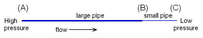 The flow-rate depends on two things, 1) the pressure difference between (A) and (C), and 2) the total restriction of the pipe.
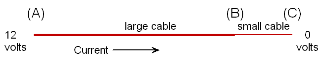
Electrical circuits are almost the same.
In electrical terms, we have Voltage (the pressure), current[amps] (the flow-rate), and total resistance[ohms] (the restriction of pipe circuit)
 Every electrician knows Ohms law intuitively –
v = i multiplied by r or volt difference = amps x resistance[ohms].
However, heating does not have a commonly known equivalent
e.g. pressure difference = flow-rate x restriction
The reason why electricians have it so sussed is that they have the tools to know exactly what is going on in every circuit. A volt meter can show the voltages at all points in a circuit. A current clamp can show the amps that are flowing. We can easily know exactly what is going on in any cable.(e.g the voltages at points A,B & C)
Plumbers have no such luxury. We would need tapping ports at various points around a circuit if we want to know pressure differences. We only know the static pressure at one point, which tells us nothing. Furthermore, we generally have no idea how much is flowing in each individual pipe run. There is also no easy way of measuring the resistance of a pipe system, so there is no easy resistance equivalent for pipes and fittings. All-in-all, the heating engineer is very much in the dark, and would have little idea what the pressure is at point (B).
Now let’s consider a simplified scenario that an electrician might face –
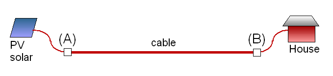 Here we have a PV panel at a long distance from a house. It will make perfect sense to any electrician to have a very thick long cable from (A) to (B), whilst having relatively thin cables at each end. The important requirement here is that the total volt-drop due to total cable resistance is kept low. For every metre of cable, there is a very small volt drop, and all these add together. The calculations can easily show the volt-drop. You can use a cable calculator on-line.
It is the LENGTH here that is the issue. If (A) and (B) are close, that section could be thin, but if the cable is long, it need to be fat. If the cable is very long, it needs to be very fat. However, making the short ends any fatter will make very little difference to the total volt drop.
Back to our water pipes,
The same thing applies. Every metre of pipe causes a pressure drop (when water is flowing), and every metre adds up. Again, it is the LENGTH that is a major issue here. For example, if you have say a 5m length of pipe and you need 1m head of water (0.1 bar) to make a certain flow rate, then you need twice the pressure if you have twice the length. 50M of pipe would need 10m head (1 bar) to give you the same flow rate. However, it you swap that 50m long pipe for one of bigger diameter, you will have far less ‘resistance’ in the pipe. The required flow rate can be achieved with far less pressure.
You can play with an on-line calculator to see what happens with different pipe sizes and lengths. See http://www.pressure-drop.com/Online-Calculator/
It is easy to overlook the pipe LENGTH, this has just as much affect on the flow and pressure drop as the diameter does. This is why a water meter with a very small bore does not affect the flow-rate very much – it is very short. Put 10 water meters in-line, one after another, and you have a big restriction, and a big problem.
So, back to our earlier assertion that any small-bore section of pipe bottleneck is akin to the weakest link; The bottle-neck principle does not apply here in the same was as it would to traffic on a motorway. If cars acted like water molecules or like electrons, they would push bumper to bumper and shoot through a bottle-neck at extremely high speed!
I have added a page on this topic here http://heatpumps.co.uk/technical/pressure-drops-flow-rates/
An example
To finish, let’s do a little exercise on pipe sizing. Let’s look at a scenario with a 10m (30ft) high header tank is supplying a tap/valve via a large bore pipe. i.e. a good 1 bar pressure supply of water. Let’s consider extending this pipe horizontally and look at what flow-rate will emerge out the end of it. We are assuming 1 bar pressure at the start, and zero bar (atmospheric pressure) at the outlet.
We can firstly consider a 15mm (outside diameter) pipe (the most common pipe size for taps).
One 40m length of this plastic pipe would give us a flow rate of around 8litres/minute (About 2.1 US gallons/min or 1.75 UK gal/min.). This is a typical bath-tap flow rate.
If we use copper instead, the wall-thickness is thinner and internal bore is bigger. We could have well over twice the length of pipe and get a similar flow rate coming out of the end.
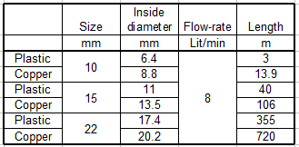
As you can see from the grid, you could go as far as 720m if a 22mm copper pipe were chosen.
If we go in the other direction and fit a small pipe, we can see that a 10mm copper micro-bore pipe that was about 14m long would still give us 8lit/min. If we now look at 10mm plastic with its small internal bore of only 6.6mm (pencils are fatter than that) then it could be no longer than 3m if we want the same flow rate to fill a bath.
This simply illustrates how the diameter and length could be adjusted to give the required flow rate given a certain available pressure. In summary, a short thin pipe may act similarly to a long fat one.
Hi John
We are in the process of looking at a heat pump system in our four bed year 2000 home in SE UK. The current heating system is a gas boiler with conventional rads which out of the wall are fed by 10mm copper microbore. Last time I was under the upper floor (addressing a leak) I recall plastic manifolds served by 22mm plastic pipes, although I cannot be 100pc certain of that.
The plan is that low temperature rads are fitted in place of the standard rads on the ground floor at least.
I am assuming that as the 10mm sections are only shorty from each 22mm manifold then I don’t need to be concerned over the issue of them being served by microbore? And that as long as the flow and return temps are kept within dt range and the pump is specified correctly things should be fine?
Great site by the way – learning a lot about this technology.
You could try playing with this pressure drop calculator to get a feel of pressures and lengths http://www.pressure-drop.com/Online-Calculator/
I guess leaving the old pipe is easier than changing it, and if your dt is only a bit greater than ‘ideal’, the loss of efficiency may only be slight.
Now that circ pumps use less energy. arguably you could use more pump power to correct for not-quite-big-enough pipe diameters.
Thanks John. We have been invited onto the OVO Govt heat trial and fitting is next Monday. A volumiser has been specificed to account for the fact we have 10mm plastic microbore drops on the ground floor only, fed by a mix of 15 and 22mm plastic and manifolds. Daikin 250 litre tank and 7kw Monobloc, heat demand 4.5kW over the whole house (triple glazed in March and added loft insulation). I will update you on how the install goes, but the installer has warned us that the 10mm may have to be replaced with 15mm if the system doesn’t work as expected. I did do a test using our Worcester 18Ri system boiler in the last very cold snap leaving it on all day at 45oC flow temp and it worked fine (leaving it on all days helps with reducing gas use too it seems) and temp drops at rads at furthest was no greater than 7oC, return Dt to boiler was only 6oC when warm which boiler not designed for!). No doubt a problem for many houses built at the turn of the millennium….
I have a Wilo Gold CH pump, fitted 7-8 years ago when I replaced my potterton netaheat with a vailiant 418 ecotec plus, since that time the boiler is constantly shutting down on high temperature target 72oC goes off at 74oC ??? When it’s not continually going over temperature and restarting it goes into Hold 5.3.3 from my own investigations it appears the flow is too low, I have to often reduce the boiler To 5-6KW just to get it stable….when stable I get 5KW Delta T 19oC outlet set at 72oC I get a calculated flow of 0.2263 m3 / Hr ( 3.6 l/min ) I can only assume that’s too low, I have 10 rads, 7 have TRVs the other 3 are fully open….the house had an extension built in 2003 I think maybe some of the new plumbing may have introduced flow restrictions, too many elbows or maybe poor routing of pipework 🤯 the problem didn’t materialise with the Netaheat, but with the Vailant defo have problems, the FE tank is clean & system cleaned and inhibitor added recently, the expansion pipe to the FE tank has been joined to the FE tank outlet by a plumber, as from 2003 had a lot of air ingress, which is now resolved, can you suggest a more powerful pump that could ease my problems
If I pay for a power flush, will I usually get. DP across the system before and after to see if there was any gain ? Also will a power flush remove any sediment in a boiler HX ? And could a bad pipe configuration be responsible for the restriction ( since the house extension ‘
Thanks
Sorry I didnt relpy… but I wasn’t sure how to.
low flow can sometimes be almost impossible to pinpoint, and I had a similar problem the other week. low flow, and no obvious reason. Not knowing what to do, I decided to look at a non-return valve in the system, wondering if it were a cheap small-bore design. It was blocked with debris, so cleaning that made all the difference. Another thing that can happen on a new system is trapped air. A pocket of air can position itself in a downward-sloping pipe. the water runs under the air pocket and is constricted. Usually it sorts itself out in time, but it is certainly a thing that has confused me in the past. Important to make pipes slope slightly upwards if possible… not slightly downwards