(Note, if you are reading this you might also be interested in my flow/pressure simulator)
A college tutor recently suggested to me that the current environment in the heating industry does not encourage analytical thinking. Maybe I should therefore be less amazed when I come across plumbers who think copper and plastic pipe are interchangeable.
Before you think I am anti-plastic pipe… I am not. The right size plastic is absolutely fine.
Environmental considerations of the materal aside, a more direct issue is that of flow rate and pressure drops. Bore size of plastic is considerably smaller than copper, and it seems that this is often overlooked. If installers select plastic pipe instead of copper without checking the size correctly, this could have a negative effect on heat pump’s performance.
(If you drop-off to sleep ½ way through this – read the scenario at the end )
With respect to the materials of plastic and copper, it would appear that the total energy involved in mining and manufacturing copper is far greater than the total energy (including the crude oil to make the plastic) to manufacture plastic pipe.
Here is one site that discusses the topic , though not necessarily without bias.
Another factor to consider, that mainly affects pipe runs to hot taps etc, is the heat capacity of the pipe material. Plastic has a relatively high specific heat, and the wall is thicker, but it’s light. The net thermal capacity of the two is fairly similar.
(The cold feel of copper is more to do with conductivity from the hand than heat capacity)
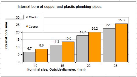
However, obvious factors aside, one of the biggest issues that could affect installations involving heat pumps relates to the internal bore diameter. This could have a very noticeable effect on the energy-efficiency of the system.
All metric pipes are measured by their outside diameter. As can be seen, with common pipe sizes (outside diameters), equivalent plastic pipes have considerably smaller internal area to copper. This has a dramatic effect on flow characteristics.
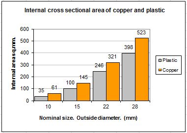
The graphs below illustrate examples of the relative internal dimensions of common pipes.
A brief note about smoothness – It seems a common belief that plastic is ‘smoother’ than copper, but the inner wall ‘smoothness’ of the two is about the same. However, plastic can be one-piece with slow sweep bends. In a different sense of the word, this is certainly ‘smoother’ than copper with tight elbows. Re inner surface, we can assume the two materials are about the same.
Whilst it is fairly easy to look-up the pressure drop resulting from a specific flow rate with a specific pipe, we can see from the 2nd graph at-a-glance the relative flow capacity since the cross sectional area loosely indicates flow capacity.
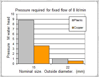
If a certain flow rate is required, then we can look-up the required pressure that is required across the pipe length (beginning of pipe to end of pipe length). The internal bore must be chosen such that the circulation pump is not overly large and energy-wasteful.
This graph shows the approximate pressure required to maintain a certain flow rate for one specific fixed length of pipe example. As can be seen, the pressure drop along the example pipe varies very dramatically, so the wall thickness makes very big difference.
In this example, we can see that a 15mm copper pipe could be used with a common central heating pump (shown at 3.6m head, 36kPa). However, if plastic were chosen, then one would need almost 9m head to achieve the required flow – far beyond the capability of normal circulators. On the other hand, if 22mm plastic were chosen, the pressure requirements would be only 1m head (10kPa) which is likely to achieve very low circulation pump energy.
In real life, we tend to have a pump connected to a pipe system, and the flow rate that results is dictate by the balance between the pressure produced by the pump and the ‘restriction’ of the entire pipe work circuit.
There is a common concern about the restriction caused by the inserts (stiffeners) needed at joints. These restrict the bore, but they are so short that the the affect on flow is much less than it may seem.
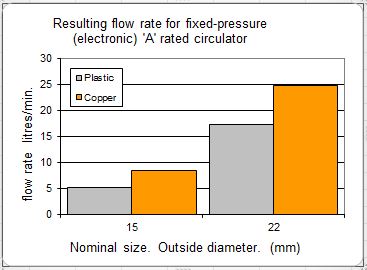
For our final graph, we consider a pipe circulating with a fixed-pressure electronic pump (Alpha etc)
The above graphs show relative changes in flow rate that would result from a fixed pressure. If the pipe chosen were too small, then a larger circulation pump may be needed in an attempt to compensate for the extra restriction caused by the small internal bore.
The point here is that by choosing plastic instead of copper of the same nominal size, the system could potentially suffer unless the sizing is checked. There is of course no problem using plastic if it’s the right diameter. Indeed, 28mm plastic may be an ideal choice for the connections from a heat pump simply to minimise noise transmission. The best final solution is often a mixture of both plastic and copper for a multitude of reasons.
All this emphasises how dramatically the wall-thickness affects flow rates and pump pressure requirements, but how does this translate into reduced COPs?
Scenario(based on something I observed on a barn conversion)
Let us consider a radiator at a far distance from the heat pump. The flow-rate relates to the pressure drop, which relates directly to the pipe-run length, and of course, the required flow-rate relates to the room size (bigger the heat demand, the more flow required). In this instance the room is large.
The default pipe size choice would be normal 15mm (outside diameter), but if the sums are done, it may become apparent that the choice should be between either 15mm copper or 22mm plastic.
How could a pipe with too small bore affect the COP?
Radiators should be balanced, in general by throttling valves (lockshield) on smaller radiators, and those with shorter pipe runs. However, this is actually quite a difficult thing to achieve with a heat pump because the temperature difference (water inlet to water outlet) may only be 5 degrees (°C). (It’s much easier to measure and adjust when the temperature differences are larger).
It is not ideal, or easy, to have to throttle most other radiators on a system, and there is the added risk of the circulation pump not being big enough to cope.
The likely result of any ‘restrictive’ pipe-runs would be a reduced flow rate to the radiator. This would result in a considerable area (the bottom) of the radiator being cool, and a reduced heat output to that room.
The obvious action to redress the short-fall of heat would be to increase the flow temperature by increasing the heating curve setting of the heat pump. i.e. increasing the flow temperate from say 40 to 45°C. Now the heat pump has to heat ALL water to a 5 degrees higher level. This is likely to reduce the COP by 10 to 12%.
This all indicates that one must never assume copper and plastic are interchangeable without considering the pressure drops and diameters. That aside, we have also highlighted the importance radiator balancing. Ideally the pipe runs to radiators would be laid out, and bore sizes chosen so that the flow rates are naturally about right without the need for much valve adjustment. A little extra work on the design makes life much easier thereafter.
Anyone intersted in further reading on water flows – this site is very interesting
http://www.johnhearfield.com/Water/Water_in_pipes.htm
Here you can enter pipe sizes and find out the pressure requirements to achieve a certain flow rates.
And here
Hi John.
I’m installing heat pump(s) as part of a significant house refurb and am researching piping to be used in two particular areas;
1. From heat pumps to buffer tank. I am looking at 2 x 14K ASHP’s. I have seen that the recommended flow/return pipe size for each pump is 28mm (in fact I’ve seen figures that suggest it should be 35mm but that’s another question). I’m considering using Pex-Al-Pex (PAP) pipe for ease of running, bends vs elbows, and cost. 32mm PAP has an ID of approx 26mm so about the same as 28mm copper. At each end of the run of 32mm PAP where I need to convert to 28mm copper the fittings involved have a brass sleeve that fits inside the 26mm ID PAP pipe much like a Speedfit type insert. I’m awaiting confirmation on dims but I’m guessing the ID of the effective inserts will be around 20mm? Should I be worrying about the restriction these ‘inserts’ will impart or, as I have read in your posts, does their very short length (guessing around 20mm) make this a non-consideration? Pipe runs will be around 20m
2. Related but different application, again considering same PAP pipe for the pipework around the home. 32mm PAP for backbone of system where 28mm would normally be used, 25mm PAP (ID 20mm) in place of 22mm copper and maybe 20mm PAP (ID 16mm) in place of most 15mm copper. In doing so I hope to avoid a lot of elbows replacing with gentle bends, be able to run pipes through holes in joists rather than weakening notches etc. there will however be some restrictions in any necessary joints. Again, given the ASHP mantra that ‘high system flow capacity is king’ should this worry me?
Best
Paul
It sounds like you have thought through the bore sizes sensibly. It does of course depend on the pipe lenght. However, given the improvements of latest circulation pumps, I would argue that we can go smaller in bore for many applications now. If you are only providing flow through the heat pump and the run to buffer (radiators/underfloor have separate pump), then there may be plenty of pressure available in the pump with the unit. The pressure requirements can be calculated. Its worth consideting the internal volume of the pipe run. This is ideally low since for DHW, this volume must be heated before any cylinder starts heating, so pipe size is a compromise. I have occasionally run pipes at very high velocity without problem.
Re the inserts… you can try this experiment.. bit-by-bit close a valve until there is a measurable drop in flowrate, or rise in pressure drop/rise at the pump. it is surprising how far closed the valve can be before there is a measurable difference. so, I dont think inserts are a particulart problem. There will be known values, but my apologies.. I dont know them. Having said inserts are not a big problem, I do tend to choose thin stainless ones, and use copper as much as possible for short connecting peices… partly to reduce the number of inserts
Thanks John. I’m amazed that in trying to research the subject of effects of pipe inserts on flow rates there seems to be so little info out there. At least I haven’t found much other than comments on your own site. Your comments on efficiencies of modern pumps helping to offset this make sense, as does the consideration of system volume when considering DHW. Thank you!
Yes, it’s strange that so little is mentioned about it. I tend to avoid and/or use stainless ones, so ignore them. I have 10mm hot pipe runs here, and dont have insetrs…. thinking the smaller the pipe, the less need for insert.. maybe thats a risk?? no problem so far!!
Hi John,
Good article….but what about your thoughts on velocity and well insulated homes.
The topic does not mention velocity, but only flowrate. Is the pipe velocity not an important characteristic to avoid low heat transfer associated with laminar or transition flow regimes. The challenge is linked to velocity and inside pipe diameter. The normal/optimal flow rates mentioned tend to generate turbulent flow regimes, which is significantly better at heat transfer. If you have good house insulation and a low heat demand, then the underfloor heating circuit flowrate could be low with low velocities.
The point may be important in under floor heating systems, which tend to run with 16mm plastic pipe as standard and lower circuit flow rates.
Is sufficient heat being transferred if the pipe velocity falls below 0.2 m/s? This involves the heat transfer from the water to the pipe. The Reynolds number because important, with transition flow sitting around 5000 or less. I would guestimate the laminar flow heat transfer is approximately 1/6th that of turbulent flow regime. So it potentially distorts any heat calculations or sizing based on turbulent flow only.
To overcome poor laminar-transition heat transfer would require healthy flow rates to push up the velocity to 0.5 m/s or above. Effectively the manifold circulation pumps would have to increase flow to achieve better heat outcome in a low heat demand room/house. Alternatively, smaller bore plastic pipe could be a better design solution in this case, after checking pressure loss, etc.
So smaller bore plastic pipe may be beneficial in UFH design for low heat demand rooms. Hopefully that makes sense.
Frank
Thanks for your thoughts Frank. The topic of laminar flow has been pondered/discussed many times. In the article, I am generally considering the pressure drop caused by pipe that i.d. too small., and a bit of a dig at those assuming plastic and copper can be interchangeable.
Anyhow, re heat transfer in pipes. I once had an opportunity to run a ground source heat pump with extremely low flowrate in the collector. I could not measure the difference. I even went to the lenghts of puting a tiny thermocouple in the very centre of the pipe, and on the inner wall surface. Of course, within the accuracy of the thermocouple, I could not measure a difference between water in the middle and the inner wall temperature. I concluded that at such low heat flux (w/sqm) that turbulence makes little difference in practice.. Maybe others could do a more deatiled experiment and prove that wrong. Anyhow, back to say underfloor heating. For laminar to be a problem, there would need to be a measurable difference between the bulk water flow temperature and the inner wall temperature. I forget the figures I looked at, but thermal conductivity of water (if static) is 1/3rd that of plastic, so even if there were a thin layer of staic water, then conduction would be relevant. That said, the velicity has to be quite slow to achieve laminar flow. Water velocity inside radiators would be very low. Nobody worries about that. For high-flux in heatexchangers etc, ofcourse turbelence is vital.
Hi John,
Thanks for sharing your insights. I was too quick suggesting a 1/6th heat transfer reduction from turbulent to laminar flow. That was my mistake using too high a heat transfer load. Your correct, it is not appropriate to my UFH question.
However, I have surprised myself and performed some actual calculations for a low heat transfer load of 10W/m. I ignored the screed to gauge the heat transfer to the outside of the plastic pipe. It was too complicated otherwise!
My simple calculations suggest the inner wall plastic pipe temperature difference is very small based on 34C water. It ranges between 0.3C (transition) to 1.0C (fully laminar). The fully turbulent flow regime has a temperature difference of 0.1C at 0.9 m/s. So that appears to fit your own experience of no detectable difference in temperature measurements.
The calculations also suggests a heat transfer drop of ~50% when flowing at 0.1m/s (fully laminar) when compared with 0.9m/s. The start of the transition flow regime shows a less dramatic fall of 20% at 0.2 m/s compared with 0.9 m/s, which seems to be the desired flow velocity in most piping systems.
It would seem that a very low UFH circuit velocity flowing less than 0.2 m/s should be discussed with the heating engineer.
I may be barking up the wrong tree here, but it implies an extra load requirement from the heat pump to compensate for any circuit velocity below 0.2 m/s. I know of a proposed UFH circuit velocity of 0.055 m/s with a flowrate of 0.67 litre/min. The proposed low velocity suggests an almost 50% extra demand to compensate for the poorer heat transfer laminar flow regime. The supplier was of the opinion a larger 20mm pipe in UFH was a good. Much better than 16mm pipe!
Happy to share the Excel chart if it is of any interest. Just unable to load it here.
Regards,
Frank
PS I had the thermal conductivity of water at 0.623 W/mK. I used PEX plastic pipe with 0.41 W/mK.
Like you, I only do simple sums for things like this… like estimating temperature difference across the plastic pipe.. ignoring the thin aluminium etc. I do wonder if the classic immage of laminar flow actually happens, as its shown in theory… e.g. a small region of high velocity in the middle, with increasingly slower velocity water as we reach the pipe wall. Theremal conductivity could play a part, and I dont know what happens at each return bend. Anyhow,… so for a normal High-ish velicity underfloor pipe I think it reasonable to assume the water temperature is so close to the pipe temperature, it can be ignored. So lets assume the pipe is 35C. In order for COP to be affested, the water would need to be notably warmer than the pipe surface. So is we have a big pipe and very low velocity and a pipe surface of 35C, would it be possible for the water to pass through the middle of the pipe, several degrees warmer than the pipe surface?? Every 1 degree rise could cause a COP decrease of 2 to 2.5%. https://heatpumps.co.uk/cop-estimator/
Hi John,
Thanks for the information on the likely drop of 2%-2.5% in COP for a +1C water rise.
For my part, I will try and avoid UFH velocities below 0.2 m/s in the design. At least I will avoid 20mm UFH pipe!
In my experience from another industry. The 90 degree bend does create a local flow disturbance that should encourage more turbulent flow and better heat transfer. However, these local flow disturbances tend to dissipate after 10D ( 120mm in 16mm od pipe) and revert to the straight pipe laminar flow regimes for low velocities. So it should not have a big influence on a 4m length of pipe.
If you have smooth plastic horizontal pipe, then laminar flow should be possible in theory/practice for very low velocities. If the pipe bore is very rough or grooved, then that’s a different story.
Regards,
Frank
Hi John,
Interesting post.
I am not sure if this adds any value to your post, so please feel free to share or ignore in equal measure.
In my opinion, you take a sensible position on inserts and the small impact it has on system performance, depending on insert size. It really depends on the insert inner diameter relative to the plastic pipe inner diameter.
If the insert is viewed as a flow restriction orifice. Then it generates a local pressure drop depending on the size of the insert to inner pipe diameter ratios (d/D).
What influence could this have on the overall pressure drop and pump capability?
For water with a 0.9m/s nominal pipe velocity. The pressure drop across the orifice ( or insert) is 0.25% for a d/D of 0.89. It approaches 9% with a d/D of 0.56. That 9% pressure drop is per insert and represents a large restriction in practice. Eg a 10mm insert internal diameter within an 18mm pipe internal diameter. The restriction orifice information can be found in typical process or instrumentation websites.
Regards,
Frank
Yes, I’m sure a lot of people (including me) ponder about inserts and their affect. I dont think the pressure drop can be calculated due to the affect of size-change, and turbulence caused. I have always favoured stainless rather than chunky plastic ones. To minimise the number of inserts, copper can be used where possible for short connecting pieces. Anyhow, as you imply, the net affect on flow rate is often imesurably small, and is less a problem than it firts seems
Assuming that the column of water has cooled and no other taps connected to this 22mm pipe have been used then you will get hot water in approx 1/4 of the time it took previously, also you will waste only 1/4 of the energy lost in the unused hot water standing and cooling in the pipe.
Dear John
I an upgrading my combination boiler (to another combination boiler) following a loft extension (new shower & bedroom) as the current boiler is not powerful enough to heat the house (4 bed 2 bathroom to 5 bed 3 bathroom following conversion). I would like the new boiler to allow the running of two showers or a bath/shower, shower/tap simultaneously which it currently cannot do.
The current pressure is 2 bar and cold water flow rate is 12 litres per minute at the kitchen sink. There is a 4 metre length 15mm diameter lead water supply pipe attached to 15 mm copper pipes in the cellar. The flow rate at the stopcock at the edge of the property gives 25 litres per minute of water but this falls to 12 l/min by the time it gets to the kitchen sink. All internal stopcock are fully open.
How can I increase the flow rate of the cold water by increasing the supply pipe size? Do I also need to increase the size of the 15mm copper pipes from the cellar to the new combination boiler (10 metres in length)? What size pipes do you recommend to get a flow rate of 25 litres per minute and 17 litres per minute?
Best regards
Michael
Hi John and DRMB,
Firstly – thx John for the very interesting article. Its the best info I have found on a confusing topic with lots of conflicting views everywhere on he internet!
I’m refurbing my house and want to future proof it for a heat pump once my newly installed combi gives up in a maybe 10 years time. So like DRMB I’d like to change my pipework (its mostly 15mm. I’ll probs go for 28mm for the bulk of the heating. But the thing that’s puzzling me is what should I do for the water pipes to the showers / bath rooms?
– Will the showers/bathrooms benefit from larger bore pipes, or are these all fine at 15mm for an ASHP?
– if there is a benefit for ASHP hot water heating increasing to bigger bore (I could run 28 if it means I get better pressure in the showers), will my standard combi work as well when pushing water to the shower in the meantime before I convert to ASHP?
Any thoughts / views you can throw onto this scenario would be most welcome.
Best wishes,
Chris.
Thank you very much John, that's reassuring – and using the calculator seems to confirm that the effect of the inserts won't be material. Much appreciate your advice.
Hello Steve, yes, you would expect a bottleneck to reduce all the flow, but water is not like cars on a road. The pressure drop equates to the sum of the pressure drop of every bit (length) of pipe, so a short restriction does not amount to much. A long section of thinner pipe amounts to a lot. It can seem counter intuitive. I dont actually know how much the inserts affect things, but its not a great deal. That said, I often choose the stainless ones instead of the plastic ones. They are usually the same outer diameter.
Have you looked at http://www.pressure-drop.com/Online-Calculator/
you can type in your lengths and diameters and look up pressures. This is really useful. For the inserts, there will be an added drop due to the change in diameters, anyhow, you could simply experiment with it. (you will need to add roughness which I usually use 0.0014)
Whilst the science of fluid dynamics can be complex, it can also be deadly simple. You simply need to use pressure drop/flow charts and make sure you know the inside diameter.
good luck
Hello John, thanks for your interesting blog. I wonder if I can bounce a further question relating to plastic piping off you? In essence, it's about whether one narrower bit of piping in the middle of the supply length acts as an absolute bottleneck (as seems intuitive), or whether its effect is proportional to how long it is (which is what I have a vague feeling that physics might say).
I have a 5m length of 22mm plastic "Speedfit" pipe which connects my shiny new 32mm water main to my internal 22mm copper piping in the house. But it's been pointed out to me that these snap-together plastic systems use a small 15mm insert inside every connector/elbow/joint. There are probably 10 or 12 inserts in the 5m length of pipe. I'm wondering if simply having ANY constriction down to 15mm acts as a bottleneck, meaning that the maximum flow rate is instantaneously throttled back?
Or, is it that any reduction in flow rate is proportional to the LENGTH of pipe which is of the smaller diameter, in which case I guess I've got about 12x3cm of the narrower inserts, so only about 36cm of effectively narrower pipe, which is probably not too big a problem? I see from John Hearfield's excellent webpage that this might equate to about 7x36cm of 22mm pipe, so it's like having a further 2.5m of pipework in the system, if it were all the larger diameter.
Hope that makes sense, and thanks in advance for your thoughts.
Steve
Bear in mind the website is desperately in need of a bit of refreshing. I need to make some time to do that.
John
Hi John, many thanks for your prompt and simple to understand answer. I shall read your web site some more and hope to retain the information and then spread the word!
cheers
Martin
Hello Martin,
The fact that your tap is constricted doesnt matter because its only a very short length. The flow rate is a result of ALL the pressure drops over the entire pipe run. If you had 1/2mile of 22mm pipe, you would have a low flow since the tiny drop over each meter adds up to a big pressure required to 'push' it through. If you have 1m pipe run from the header tank, the pipe could be maybe 8mm o.d. ?? My guess is that a 10mm pipe would be enough for your kitchen sink, but different people have different idea of 'adequate flow'. You can buy 12mm pipe as used for caravans – that might be safer.
If you had 3 bar of pressure, I'm sure 10mm would do.
I do discuss this along with some suggested flow rates in my book, also its on my website.
Yes it is annoying that many people overlook this. Many new houses still have to draw off lots of water before it 'runs' hot. Passive house are the only people who seem to be embracing the issue
Hope it works out OK
Hello, I’m really impressed by the various blogs you have written, even though my full understanding is limited by my technical capabilities. I have a question for you that I hope you are able to answer.
I live in a three-storey town house where the pressurised (about 2 bar) hotwater tank is installed in the loft, a 22mm plastic pipe feeds the basins, bath and shower on the 1st & 2nd floors and the kitchen sink on the ground floor. The kitchen sink is therefore the furthest from the hot water tank and the column of water in the 22mm pipe leading down from the hotwater tank is therefore significant and must be drawn off before hotwater can reach the tap. Given that the thread size into tap for the tails is 11mm, and the internal bore dimension is approximately 8mm, the amount of time to draw off the cold water is fairly lengthy. It is also a waste of water.
My question is this: would fitting a dedicated 10mm pipe (plastic) from the hotwater tank (well, spurred off from the 22mm outlet pipe) to the kitchen tap tails deliver hotwater to the kitchen sink quicker and without loss of throughput (given that the tap tails constrict flow anyway)?
I did pose this question to the technical team at Franke (the tap manufacturers) and their response was a disappointing ‘what are you talking about?’. My plumber’s reaction was much the same, but given he used a hammer to make a hole in the floor for a waste pipe, I’m not surprised.
I trust that you can provide a simple to understand answer!
Hello Martin,
I work in an area of London where many 3 storey Victorian houses have their hot water tank at the top of the house. I always recommend to clients that we fit a 10mm plastic pipe from the hot tank down to the kitchen 2 floors lower.
Measuring the water at the kitchen sink until water runs hot shows a saving of around 2 litres, and sometimes more, each time the tap has used. This is saving not only water but the energy to heat it.
The flow rate is fine whether the hot tank is an unvented (mains pressure) tank or a traditional vented tank supplied by a cold water storage tank in the loft above.