The most common and popular Air Source Heat Pump (ASHP) is the monoblock type that produces water, piped into the house for use in conventional radiators or underfloor heating. In the UK, blown-air heating is uncommon. However, an alternative type of heat pump (air-to-air) does exactly that – it heats the air directly. The Air-to-Air heat pump is derived from air conditioners, and is common in offices as a reversible heat pump that can cool in summer and heat in winter.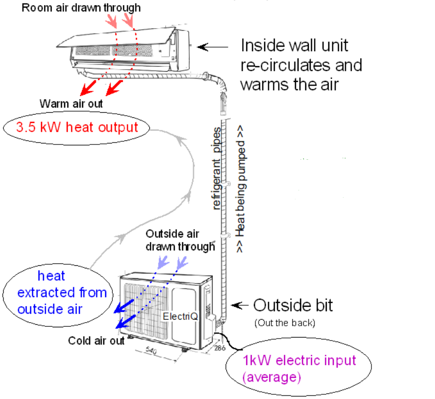
There is some debate about the effectiveness of these systems for the home. They could be a little noisy in a living room, and the air movement could cause undesirable draughts. However, some people find them very effective, and they are relatively cheap to install.
I have read some very varying claims about the energy-efficiency of these systems, hence this study on a low-cost model.
Brief Summary of findings
Air-to-air heat pumps have a fairly comparable COP to the common air-water type. However, the COP varies considerably over its high/low range. Dont just read a COP rating without knowing what outside temperature and compressor speed it refers to. Cheaper units are likely to be a worse, especially at times when defrosting is needed. Budget units like this seem to be let down by poor control, and the quality and efficiency will vary greatly. It also seems that some are not really optimised well for heating. However, their fast response and simple configuration could give them the edge for some applications. Air movement could lead to discomfort for some, though a slightly higher room temperature may counter this. A good positioning of the indoor ‘blower’ is vital…. You probably don’t want to sit under it. Though this summary might sound a bit negaitive, there are many situations where air-air can be an ideal choice if ‘driven’ well, and no doubt products are improving in the right direction.
Estimating the energy-efficiency (COP) of air-air heat pumps
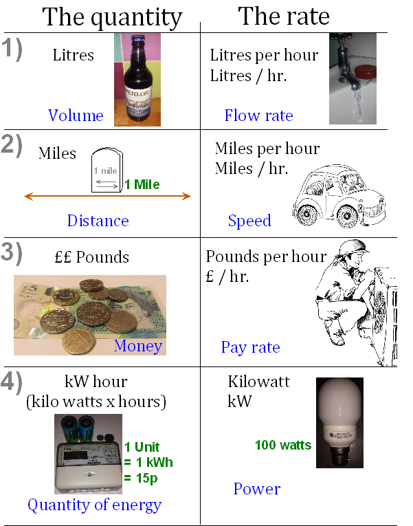
It is fairly easy to measure the heat quantity (kWatts) of a device that heats water. We can measure the water flow-rate accurately, and also the temperature rise accurately (Outlet temperature minus Inlet temperature). We can apply a simple formula –
Heat (kWatts) = Flow-rate (lit/second) x Specific Heat x ( Outlet temp -Inlet temp )
Air however is very difficult to measure accurately since the flowrate and temperatures of both vary over any air-outlet register. Humidity affects it too. One approach is to do comparative test inside an environmental chamber, but this is impractical for most.
Alternatively, we can look at the compressor and refrigerant conditions inside the heat pump to estimate the heat quantity being transferred. This is how many of the manufacturers on-board COP estimators work using their specific compressor data.
There is a general formula that the French scientist Sadi Carnot worked out 100 years ago. This gives the theoretical efficiency of a heat pump.
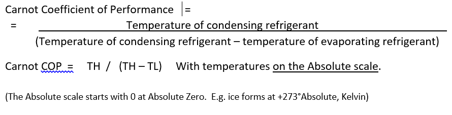
In practice, a heat pump in operation can achieve about half of the theoretical (Carnot) COP.
On https://heatpumpmonitor.org there are over 100 fully monitored Air Source Heat Pumps. We can see accurately-measured COP values here, measured using class-II heat meters, and we can use this accurate data to verify estimates using the Carnot equation – they agree well.
Simply measuring temperatures alone to estimate evaporating and condensing refrigerant temperatures (TH & TL), and then using the Carnot equation, we find surprisingly good correlation with measured COP in practice. We observe the measured COP to be between 45 and 55% of the theoretical Carnot COP, and for any specific system, variations in operating temperatures correlate with Carnot COP very well.
We can therefore look at the refrigerant temperatures of the air-air unit, and get a reasonably good idea of the COP we should expect, and how it will vary as the weather changes etc.
How can we measure refrigerant temperatures?
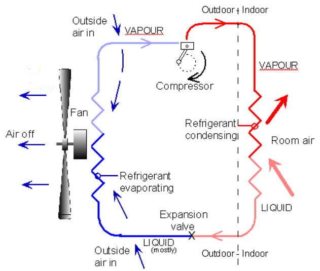
The diagram shows the refrigeration circuit of an air-air heat pump. The evaporating and condensing temperatures are measured at points where we expect the refrigerant is neither all-liquid or all-gas, but is in the process of changing state. Small electronic sensors are used here.
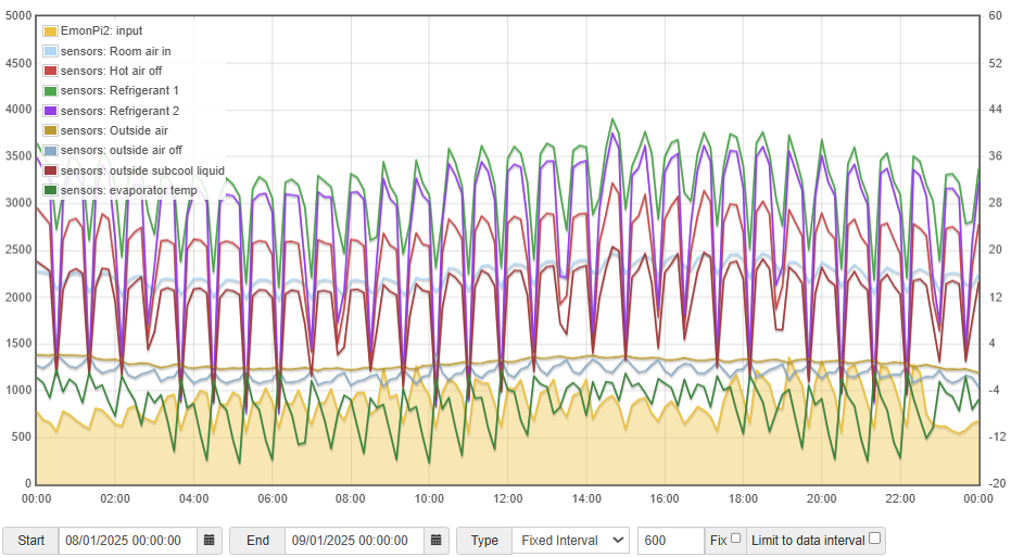
The graph (below) is taken from https://emoncms.org/thehub on February 3rd 2025
It shows a 17hr run period, using 15kWh of electricity. (approx. 800 watts average). It starts at a high level, and the air temperature set-point is dropped twice over the day, resulting in periods of high, mid, and low power.
The COP is estimated from the carnot equation using the measured refrigerant temperatures. The ‘heat’ is estimated by multiplying this by the measured power input.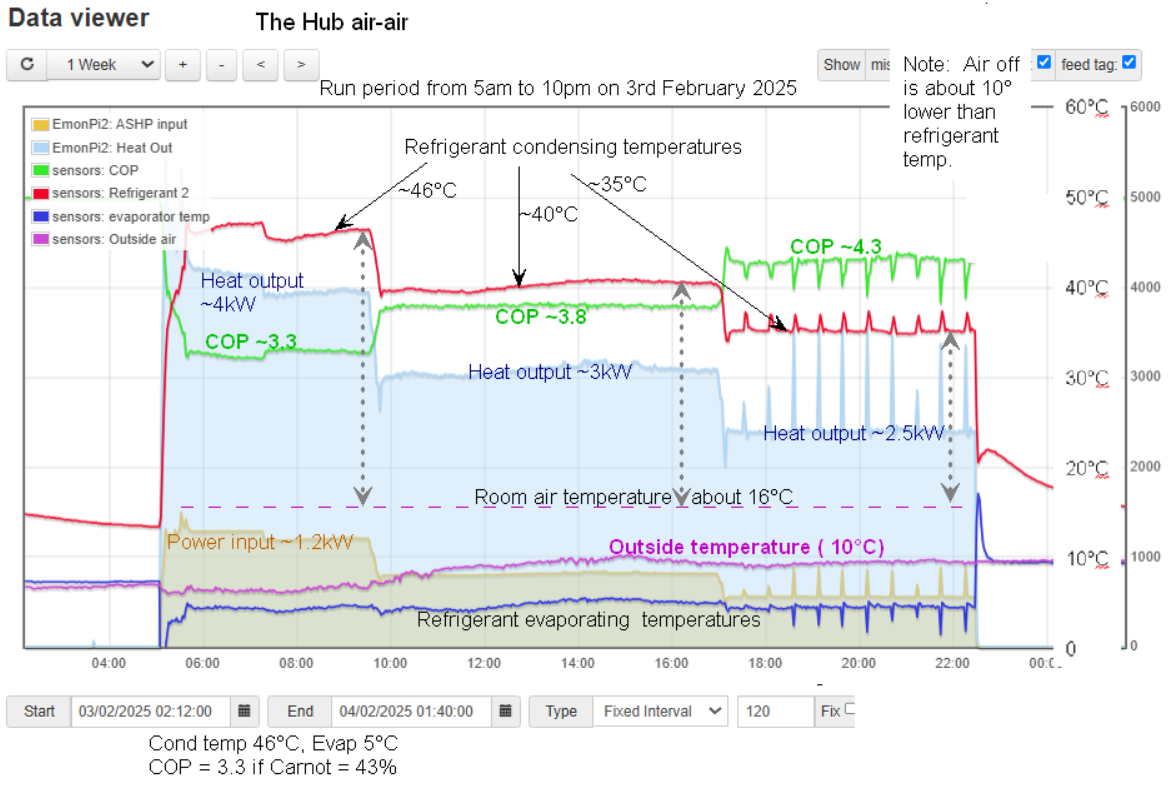
The Condenser (the indoor ‘blower’ unit)
We can see that the hot condensing refrigerant temperature drops over the day as the power drops.
The three dotted grey vertical arrows indicate how much warmer the condensing refrigerant has to be in order to dissipate that heat. (dts of 30° high, 25° mid, 20° low speed)
Given that the COP relates to the difference in temperature from the cold source evaporating refrigerant (around 5°C) , and the hot condensing refrigerant, we can see that as the compressor slows, and the power reduces, the COP rises. This is what we would expect.
Another way of looking at this is to consider the heat-exchanger sizes. In a fictitious imaginary world, the heat-exchanger might vary in size with the compressor speed. The more heat transferred (kWatts), the bigger the heat-exchanger needs to be. In our unit at high speed, the heat-exchanger is arguably not big enough, and on low speed it is nicely oversized (a good thing).
We can see here that the energy-efficiency is far better when the unit is on slower speed. If only we had the option to control the compressor speed as we choose, e.g. to maintain some heat overnight at high COP. Unfortunately, the only control we have is based on air temperature.
Better quality units would generally have larger heat-exchangers, and better efficiency.
The Evaporator (the outdoor heat exchanger)
The results on this unit are curious. We can see (above graph) the purple outside air temperature, and the blue refrigerant evaporating temperature below it. Firstly, we note that the temperature difference here is only a few degrees, which is good. This makes sense since the outside heat-exchanger size is far bigger and air flow much greater than indoors ones. However, we would expect the evaporating temperature to be far closer to outdoor air temperature when the compressor is slower, and capacity reduced. I think the reason for this on this particular unit is that it is optimised to be more efficient at ‘normal important’ conditions, and it is more important to ‘tune’ the system to be most efficient at high speed. At low speed, I expect that the evaporator is only using part of the available area. E.g. all evaporation happens inside the first third (about) of the heat-exchanger, and over half is ineffective with only gas in it. Good refrigerant control here (expansion valve) is key to efficient operation. It’s tempting for some manufacturers to skimp here, especially on smaller units.
Comparing air-air with the standard air-water ASHPs
There is not a great difference between the two, however, I think it’s a mistake to assume that it is any better to heat the air directly using the small ‘blower’ unit of an air-air unit.
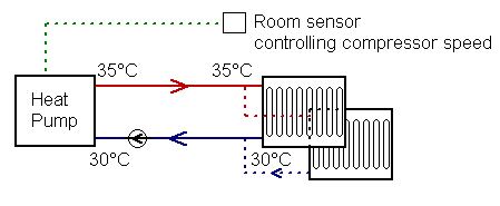
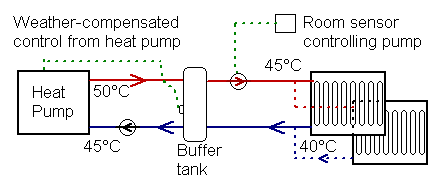
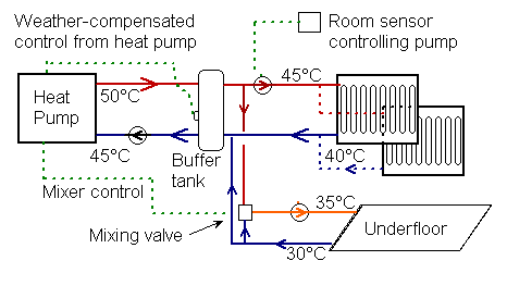
In the case if underfloor heating, we have a very large area of slightly-warmed floor. Given that water is such a good heat-transfer medium, we can operate the water in the region of 35°C (or less), and our refrigerant could condense at say 38°C. Radiators may operate at a higher temperature, and hopefully the refrigerant condenses in the region of 45°C or ideally, less.
In the case of air, we need to ‘blow’ it at a reasonably warm temperature.. like 30°C. Air heat-exchangers are not as good as water ones, so we are likely to see refrigerant temperatures between 40 and 50°C. All in all, the condensing temperatures of the two types is likely to be similar, but underfloor systems could have a considerable advantage.
One constraint is physical size. Manufacturers want the slimmest wall-unit possible. This is somewhat at odds with efficient thermodynamics. More energy-efficienct heat-exchangers need to be large.
Further to this efficiency aspect relating to the refrigerant temperatures there are other things that influence the effectiveness of a system.
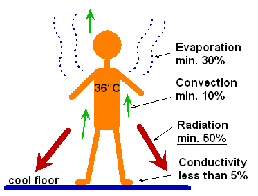
Underfloor/radiators warm the air with very gentle air currents, and radiation within the room is increased. Blown-air on the other hand has the risk of reducing comfort due to air movements. This is particularly the case for older un-insulated buildings, where more air-flow may be needed. But in practice, to ‘restore comfort’, the air temperature may need adjusting. E.g. we may choose 22°C in a room with blown-air heating, but for the same comfort in a room with a very slightly warm underfloor system, we may get a similar level of comfort with an air temperature of only 20°C.
This is of course not the only concern, and unless our house is constantly occupied, as underfloor heating is so well-suited, then the fast-response of air-air heating can make this heating method more attractive, not forgetting that radiators could have a reasonably fast response in newer buildings too.
Theories aside, it is not until we have lived with a system that we know how we would like it. I fitted a temporary air-air in my home some years ago to experiment. After several days, I took it out. I didn’t like the slight noise or the air movement.
Cooling
It’s always my beef that we don’t know how to keep buildings cool in the UK. We let the sunshine in to heat our floors etc, we open the doors when its colder inside than out.. then look to the air-conditioner to bring some cooling comfort. Furthermore, when setting the air-con thermostat, we set it ‘nice and low’. At The Hub, we found a cooling setting of 25°C was about right. It was very economic to run, and nobody even thought about it. Nobody needs to be hit by a ‘wall of cold’, as we can often experience entering an air conditioned restaurant.
Sorry…..rant over,..
It’s interesting to look at the system when it’s in reverse. The sensors I fitted are not in the best place to capture refrigerant evaporation and condensation points in cooling mode, however, it is interesting to look at.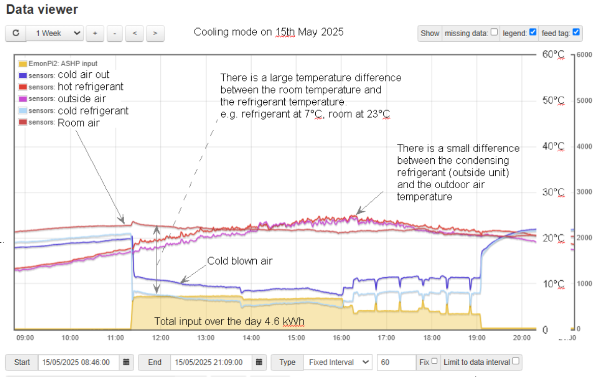
We can see here that refrigerant is condensing (outdoors) at only a few degrees above the outside temperature. As concluded before, the outside heat-exchanger is nice and big, so this small temperature difference is to be expected. However, the refrigerant evaporates (indoors) some 15° degrees lower than the room temperature. Again, we have already concluded that the indoor heat-exchanger is not ideal… it is quite small. The airflow indoors is also relatively low compared to the outside unit. Remember, these units were initially designed for cooling, and the high-wall blower positioning is ideal for that.
At The Hub, there have only been a very few occasions where the cooling function has been enabled. It’s generally not needed.
Defrosting
The outdoor heat-exchanger will form ice when the air is say 6°C or less. The system is ‘reversed’ in order to periodically melt this ice. In the case of air-water systems, during the 3-4 or so minutes of defrost, a small amount of heat is taken from the house. Air-air units cannot really do this. A brief waft of cold air would be very unwelcome mid-winter. 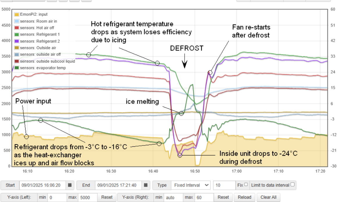 So, during defrost, the indoor fan stops and the system takes what heat it can from the inside unit. When the heat-exchanger block is around -20°C, there is no heat left to be had, and for much of the defrost, the energy is coming indirectly from the compressor motor. This results in a rather long and inefficient defrost. In our case it’s more than 10 minutes. The output is actually diminished for almost 20 minutes. Far worse than a comparable air-water unit.
Again, manufacturers may limit the resources directed to research in this area, and cheaper units are bound to have cruder control and also smaller heat-exchangers. These are more prone to frost build-up. On full power in cold humid conditions, the net heat output could be seriously reduced.
Here (below) is a 24-hr period on 8th January. The outside average air temperature is just over zero C. We can see that it is defrosting more than once per hour, and the negative affect of the defrost is very significant. It looks like half the time, the output is seriously impaired.
A quick comparison on Heatpumpmonitor.org shows air-water heat pumps with much shorter defrosts and far less reduction due to defrosting.
The worst case is freezing fog or supersaturation. Whilst quite rare, this would reduce the output very considerably. This has always been a worry for air source. The output can plummet just when most heat is needed, possibly resulting in a surge in direct electric backup. Air-air seems likely to be a worst offender here until they can develop better methods of defrosting.
Sizing
Here lies a topic that I find quite a challenge. I’m unaware of anyone accurately sizing these units. Hopefully this will change. Most sizing seems to be done based on floor area, and often heating is seen as secondary to cooling.
A worry for any installer is a customer dissatisfied with the level of heat, and a relatively small system (in terms of watts/m²) will suffer more wrt defrost, so this is a worry for mid-winter. The more it runs, the more ice build-up. A bigger unit has a bigger heat-exchanger, so icing should be less. Also, as we saw on the top graph, a large unit running slower should have a better COP.
However, there is another aspect to consider. A ‘correctly’ sized unit for the depth of winter may be over twice the size needed for the average heating-season day. Yes, it modulates automatically, but it often starts full-power. Given that the control is merely looking at air temperature, there is a tendency for the system to’rev up’ at times when this is not needed. It is even a struggle to ‘tame’ the relatively small system at The Hub. It’s not easy to keep it ‘ticking over’ on low modulation, and this would be far harder if the system were bigger.
Another issue is air movement. In older buildings like the Hub, it can be seen too profligate/costly to keep it ‘toasty’. A lower temperature like say 19° can be perfectly adequate, and we have no complaints at the Hub. However, at lower temperatures, the effect of air movement can be felt, and the bigger the unit, the bigger the draught. This then becomes a balance, and to heat the space after a lower night temperature (say 16°C) needs to be done before occupation, or done carefully and gently, or done with a blast. I think we have successfully managed the ‘gentle’ approach at The Hub, with good overall running costs, but the controls are woefully inadequate.
It would be interesting to see how the average installer and average user would cope with system similar to the Hub. The unit would certainly be considerably bigger.
My feeling is that we need far better controls for this technology to be used effectively in harder-to-treat older properties. Cheaper air-air ones are far too crude. Yes, we have infra-red occupant sensors now in better units. Are these part gimmicks or are they really what is needed?
All in all, I think air-air has some way to go. That said, I am arguably being too fussy. My tip would be to avoid cheaper units and go for quality, and do drill on to the finer details.
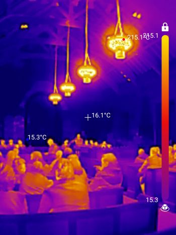 There is of course a well-established, simple and effective way of addressing this ‘shortfall’, and that is to fit infrared heaters overhead. Indeed, they are used frequently in churches, which must be the hardest of all buildings to heat, being infrequently used and with solid cold walls and no insulation. This church (thermal image) is comfortable even when the air is cool. We experience this when the sun comes out. We feel the warmth but the air is the same temperature.