Blog

Badly performing heat pumps?

Index of my blogs

Are some heat pumps performing as badly as various recent stories have been reporting?

Let’s imagine if we procured cars in the same way that some people install heating.

We could start with a body shell, then get someone to fit wheels to it, hopefully placed in the best position and sized for our purpose. We would then find an engine of a suitable power for our needs and couple it up to a gearbox with the best ratios.  We would need some way of controlling it all, and then learn how best to drive it.

In many ways, installing home heating can be little like this.  We have a ‘body shell’ that may be insulated or not. It may be lightweight or slow-to-heat heavy stone.  We then fit radiators or underfloor pipes.  Then we install a heat pump along with all its gubbins… we now have to set the controls and ‘drive’ it as efficiently as possible.

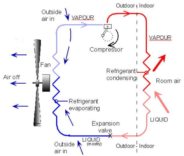
So, what is it about heat pumps that could make them prone to inefficient running?  I have likened a heat pump to a sailing boat.  You need to get a lot of things ‘just so’ in able to speedily slice through the water.  A heat pump is transferring heat from the environment, and it’s actually an amazing feat getting considerably more out than you put in (at the expense of cooling the outdoors more than it already is).  It does seem magical to get 3 kW of heat for 1kW of electricity, but it’s far from magic (my You Tube).  Let’s face it, there’s nothing magical about a fridge!

The concept does at first seem to defy the rules of science, so one might expect scepticism.  But it really doesn’t take long to understand the principle. However, if your heat pump has been pieced-together badly, you have high energy bills and are not warm enough, then you can see what feeds the notion of doubt.

If only heat pumps were as ‘visual’ as those cobbled together cars that we are imagining.  …..engines either too big or too small, either chugging or screaming at the wrong revs. How could you fail to spot the inefficiency of a car at full throttle in neutral while waiting at traffic lights.  This sort of thing can happen to a heat pump unnoticed.

I’m sure if anyone pointed their finger at such an inefficient car, the obvious answer would be – “make some modifications and get it working properly”!  The cheap-to-run cars would at-a-glance look and sound impressive.   Hopefully everyone would look to these best-performing cars and realise that they are the way forward.

It’s been odd for me seeing recent press reports that speak as if heat pumps are a new idea. In many ways, heat pumps are technologically advanced. They have been in common use in countries like Sweden for over 40 years.  A vast amount of product development has taken place in America and Japan, to name a few, so we have a great variety of tried and tested products available.

We also have, of recent years, got good training courses and knowledgeable installers able to fit them.  We seem however to sometimes be falling foul of the pitfalls with respect to how we integrate this technology into our motley (with respect to energy… no offence) range of dwellings.  I think we should acknowledge that many older buildings will be a challenge, but I feel it will not take long to learn what works and what doesn’t… we should already know!

So, how fussy are heat pumps?  What can go wrong?  In a nutshell, it’s a lot to do with the temperature of the water being heated. They love lukewarm water and whilst they can manage ‘hot’, they don’t particularly like it.  It’s simply a bit more tricky and expensive to install a heating system in older buildings if you are working with warm/hot water rather than very hot water.

So, what actually goes wrong in these underperforming systems?  To name a few….  heating cycle duration too short and too hot, heating zones switching on/off unsynchronised, house allowed to cool off too much overnight, mixing valves ‘diluting’ the water temperature, circulation pumps running when not needed, flow-rates too low.  Furthermore, given that we sometimes can only guess the actual heat-loss U values for older buildings, worst-case assumptions might be used.  This may lead to a large-size heat pump that could compound the above problems.

We have learnt a heck of a lot over the recent decade, and given that a lot of heat pumps have either heat-meters and electric meters, or on-boards performance (COP) estimators, there is no reason why we should not be able to know with good certainty how well heat pumps are performing in practice, and how we can ensure that all installations achieve their potential.

I have on occasions come across owners who have fallen out with their heat pump so badly that they don’t give them a chance… they don’t even try to get them working properly.  Hopefully, as time passes we will learn to avoid the pitfalls, and correct those that have already happened.

Index of my blogs

Heat Pumps and domestic hot water

(Index of other blogs)

Before I start, I hope nobody takes from this that we shouldn’t do domestic hot water (DHW) with HPs.  And as things evolve, I’m sure that we will do more of it, and do it better.  However, I was pondering the issue of mass adoption of HPs for smaller houses and how we tackle DHW in the immediate future.

Many years ago, when heat pump components were less developed, providing energy-efficient hot tap water (DHW) with a heat pump (HP) was a struggle.  However, it’s not difficult to add the feature since in its simplest form all you need is a diverter valve and a cylinder with large-area heat exchanger coil in it.  Even if the DHW might have had a COP as low as 2 (at that time), it seemed worth it.

It took me quite a few years to acknowledge that the losses associated with cylinders and distribution can be considerable.  We often hear claims that boilers are 90% efficient, or heat pumps (at 60°C) have a COP say 2.5, but if we look at the actual heat delivered to your bath or basin, then both of these figures could in practice be halved in a few cases, or possibly considerably worse. Ironically, frugal users have the lowest COP because the losses are a greater proportion of the total. (this doesn’t of course mean you save energy by using more water!!)

When I get the opportunity, I often run a hot tap in a house and see how long it takes for it to run-hot. Sometimes a whole basin is filled with cold water before the hot emerges.  We could in this scenario, get one basin of useful hot water for two basins draw-off from the cylinder.  This experiment demonstrates 50% efficiency, and effectively halves the boiler or HP efficiency.   The more that is used (in succession), the smaller the proportion of loss.

It’s not only the old houses with a 22mm main artery hot water draw off where the problem lies.       I am amazed how bad some new build is.  Surely pipes should take the most direct and shortest route…. Seemingly not.  Surely we would go for the smallest bore pipe that still gives adequate flow.  If we did, there would be a better range of pipe diameters on sale.   Excessively large bore pipes are a waste of water and heat, but arguably the heat is contained within the house, and is at least useful in cold weather.

For those of you thinking of lagging hot pipe runs… think it through. Sometimes the benefit of this is minimal.  e.g. after 30 mins most heat is lost regardless of insulation thickness.   Pipes around cylinders are however always hot, and these definitely need insulating well.

Pumped circulation loops are another thing.  This is a necessary evil for large places like hotels, and at least provide hot water immediately a tap is turned on.  I have limited experience of these… only bad ones.  I’m told this can be done well, nonetheless it’s potentially a big waste of energy so they need careful design and very good pipe insulation.

Loss due to pipe runs is one thing, but another is of course the heat loss from the cylinder, this heat is again arguably beneficial for much of the year. Even with no draw-off, a heat pump can spend a surprising amount of time simply topping up the cylinder.

Out there in the real world, I don’t actually know how bad these losses are, but feel they could be surprisingly bad in many cases, but hopefully many are acceptably good.  It is sort of bizarre that manufacturers optimise heat pumps to get the best COP, but on site, but some aspects need for energy-efficiency often seem overlooked.


Anyhow, with the thought in the back of my mind that DHW from a HP might be not as good as we often assume, I was pondering the issue of mass adoption of heat pumps.    One issue for smaller houses is the lack of cupboard space for a DHW cylinder.  They have not had one with the combi boiler, so why would they accept one with a heat pump?!

If cylinders are unacceptable, would it be a backward step to install a space-heating-only HP system and electric point-of-use DHW? (non-storage type that is). I don’t know, but there are some Advantages

  • No space lost due to a cylinder
  • Heat pump system extremely simple
  • considerably cheaper to install

Disadvantages

  • you still need to install several instant point-of-use water heaters… more total electric supply required from distribution board and more cable runs.
  • Higher peak load on mains supply, but this would be spread by diversity

Ironically, those small houses that really won’t welcome a cylinder, could also have short pipe runs, so my argument about long pipe losses doesn’t hold here.   It’s actually larger houses where the long pipe runs can be very lossy.  Hopefully the installer thinks it through, and doesn’t (for example) run a hot pipe to a distant hand basin.

Some cylinder-related details to sort out

Another possible headache relating to heat pump DHW cylinders is the need for safety blending valves. And this is sometimes needed because of the required periodic legionella pasteurisation. These mixing valves usually allow some cold water to pass. This means the cylinder needs to be stored at a higher temperature to combat this cold ‘seepage’. Higher temperature means lower COP.  We need safety mixing valves that can shut off the cold completely.

The ‘thermal store’ type arrangement, where water heats instantly as it passes a store, can mitigate many of these problems, but it can have its own inherent losses. This type of storage arrangement could be the way things develop.  Who knows!

Phase-change storage could be a solution to the lack of space issue, but I feel there are a few challenges here. Namely that the phase-change often happens at a high heat-pump-unfriendly temperature, and conducting heat in and out can be an added problem.  Early days I feel.

Another element to this discussion is the quantity of water needed. If a house uses a lot of hot water, then the losses due to cylinders and pipes may be a relatively small proportion of the total, so HP-heated DHW would be advantageous.  It is ironic that frugal users score badly for overall efficiency.  If water use is low. Point-of-use (COP=1) might be the best option.

Whilst large houses surely use enough water to warrant heat pump heating, it is these that where the biggest challenges arise from large distances distributing water.  I feel that this is where research is needed.

I’m not really sure how I actually sit on this whole topic, but we seem to still be in the ‘finding out’ stage with heat pumps… finding out what is most viable and most practical, so we need to try things out on all fronts.   I can think of two small houses right now that could benefit from ASHPs feeding the existing radiators (with some size tweaking), and it would seem disproportionally expensive and complicated to add DHW to the install. One has an electric shower only.. no bath.    I can also think of older houses that really need the whole hot water distribution pipework renewing to save energy. This could be very disruptive and expensive.

On the other hand, I can think of more situations where a hot water cylinder is surely a worthwhile thing.  If nothing else, houses with any form of Solar heating… this needs storing somewhere!

Improvements

Back to the actual heat pump, there is a thing called a de-superheater.  The concept has been around since heat pump started.  In essence it’s a heat-exchanger fitted to the compressor hot outlet pipe.   In simple terms, you can get say 10-15% of the heat at a higher temperature whilst also space heating or cooling.   Ecoforest offer this feature in their HTR version of GSHP.  I hope other manufacturers have this offering too.   In the past, I have felt it a case that manufacturers are driven by costs, and added manufacture cost are not welcome, but as a customer, this would be a feature I would like.  Systems with integral cylinders should be benefiting from relatively minor changes. I’m not aware of it, but maybe they are starting to do it already.    I am hoping that we see more developments like this.

For now though, I think more focus is needed on pipe distribution.   This should be basic good housekeeping.

There is a bit more about the basics of DHW here https://heatpumps.co.uk/types-of-heat-pump/domestic-hot-water-dhw/

Is a reversible air-air heat pump a proper heating system?

Index of my blogs

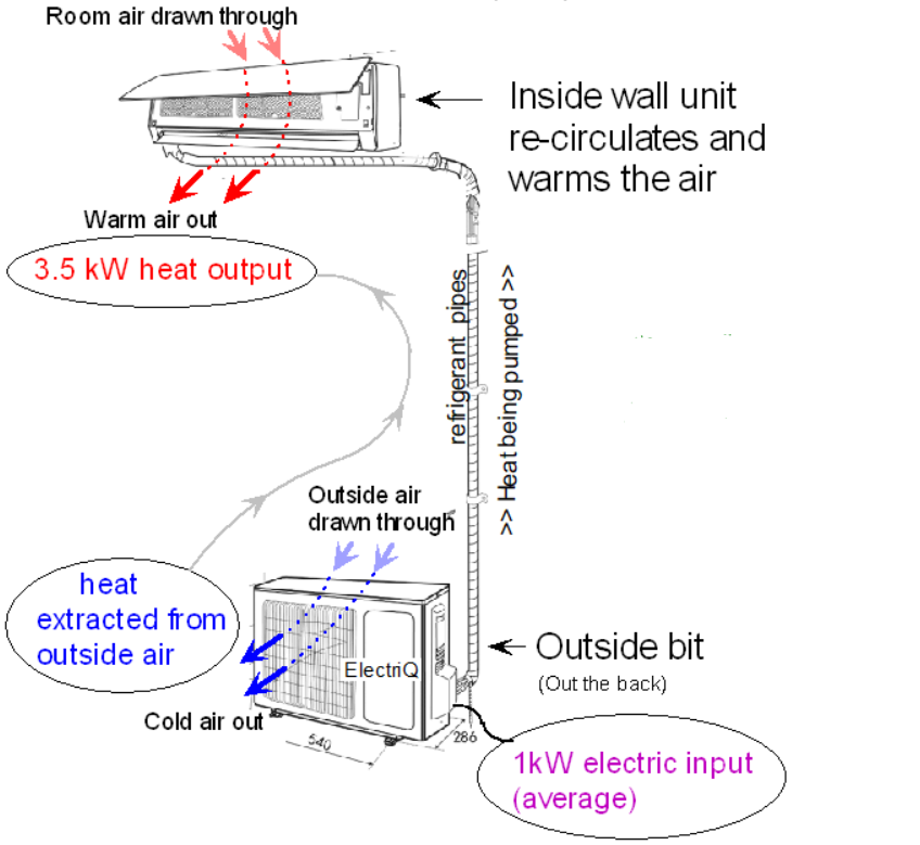
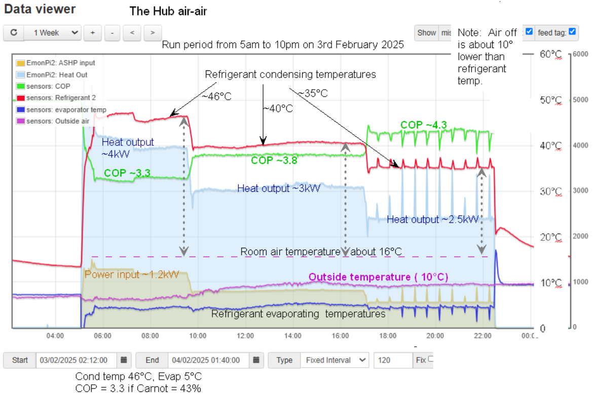
I have pondered this many times, and indeed, a district council once asked me this very question. They ended up getting me along to analyse why some of their tenants, who had this type of split reversible air-conditioning, had warm houses, low bills and loved them, whist others hated them, complained of draughts, noise and high running costs.

The tenants who experienced success seemed to be mostly one-person occupants who arranged their rooms to avoid the draught from the ‘blower’, but also who left the unit enabled fairly constantly, and who opened/closed interior doors appropriately so the warmth spread accordingly.

Those that hated them had got to that conclusion early-on, so didn’t give them a chance. however, I could see how they disliked them….. a draught blowing over the settee, and with no easy change of settee position, the owner then switched the unit on and off frequently.  i.e., waiting until they were quite cold before switching on, then it goes to full-power, and full-draught.  With guidance and confidence, the user could have improved matters, but there was seemingly no way to win them over.

So, that little exercise didn’t really answer my initial question, only to confirm that this type of ASHP can work surprisingly well in some situation, but not in all.

This actually prompted me to temporarily fit a small unit in our kitchen/lounge, so as to live with it briefly.  I concluded that I would not choose it as a heating system.  The gentle draught and the slight hum were unwelcome.     I removed it within a few days and installed it in the log cabin it was intended for (they loved it, and still do)

I was reminded of the first heat pump (air-air) that I ever built. It was in my parent’s kitchen (in 1979).  When first switched on, the air actually felt a little cold, but then oddly, after ½ hr the kitchen was actually getting warm.  By slowing down the air flow, I improved the perception a little, and fitted a time clock so it could come on before we got up. I have no idea what the COP was, but it certainly made a comfortable kitchen, albeit with a sluggish start.  I certainly had no intention of making it bigger since it did cycle on and off a lot on milder days, and in that respect, it could have done with being smaller.  No variable inverters in those days!

In hindsight, I wish I had given more thought with respect to the sizes of all the units I had observed.  Size, that is, compared to actual heat requirements (heat loss) e.g., the watts/sqm.

Blown-air heating is not very common in mid/northern Europe, but very popular in warmer countries.  I have always believed this to be because air movement is great for people cooling, but generally undesirable for heating.  If your winter is short-lived, you can put up with a bit of a draught from your heater, but if your winter is long and sometimes deep, then surface (floor or radiator) heating seems better.

This issue of using blown air for heating reared its head recently with respect to a small community room about to be built.  This is a well-insulated new-build, so total heat demand would be low.  A rudimentary heat loss calc indicated around 1.5kW of heat was needed, which equated to about 42w/sqm, which seemed the sort of size I was expecting.   Radiators or underfloor with a normal (to UK) ASHP seemed too expensive to install and even the smallest unit would be far too big.

I suggested that quotes for installing a reversible air-air heat pump be sought, and back came a recommendation for a 5kW unit.  I was a bit aghast at this.  It felt to me a bit like putting a 3-litre engine in a small city car.

I had initially thought that a 2kW unit might potentially too big and might cause a draught issue! My worry here is that anything remotely as large as 5kW must have a fairly large draught. You cannot dissipate 5kW without a reasonable breeze.   I realise all units modulate down (inverter), but my 1.5kW estimate was for sub-zero conditions, and much of the year, the heat need would be a small fraction of 5kW.

My experience with ducted air systems is limited, but the most successful one I recall was a Danish-design house that had tiny air flow because the house was highly insulated.  These systems gently blow in a small amount of warm air, and the house is never allowed to cool down much.  However, the only reversible air-conditioners that I have seen were relatively powerful.

I contacted a friend, Phil Jennings, who has fitted this type of system in his house, and has more experience than I. He shared some of his research with me (Thanks Phil).  None of the suppliers/installers that he had approached take into account the heat loss calculations. Most seem to purely go on the rule-of-thumb sizing of between 135 and 150w/sqm.   Yes, you read that correctly…. no matter how well insulated… it’s the same size unit!  This seems to be far from a ‘proper’ way to design a system.  The installers reasoning here, and possible their wisdom, might be that you cannot easily calculate a cooling load, so a one-fits-all approach would be easy, and should always provide enough ‘cool’ or heat.

So, would it be possible to fit a small air-air unit in a large insulated room, and let it simply ‘tick over’ providing a constant low level of heat?  to never expect it to be used as a fast-response, heat-on-demand system.    I doubt if any installers have tried this…. Why would they?  They may not be aware that well-insulated rooms don’t have cold corners, so don’t need much in the way of air ‘throw’.   I would have thought that a small system like this would be very energy-efficient.

As I angle back to consider the title of this blog…  ‘Proper heating system’. Is this type of heat pump ever ‘properly’ specified as a heater only?   One thing to note is that many units seem to have relatively high minimum heating set-point. E.g. 16°C.  I’m guessing that at this sort of temperature (and below) draughts could be uncomfortable. However, if I am out all day, or all week, I want to set it at say 12°C, and I feel the inability to be able to do this is environmentally a drawback.   I can see the problem, you enter a 12°C room, turn the heat on, and it feels draughty. However, I would have thought it easy-enough for the manufacturer to be able to limit the fan speed so that cold-feeling draughts are avoided.  Maybe these units are simply not optimised for energy-efficient heating.

I guess for some, the description ‘proper’ would mean a system that can keep the whole house at required temperatures, and with that respect, this might not tick that box unless that house is say open-plan and fairly well insulated.   Furthermore, the ‘blower’ is in one fixed position, and now this, in part, dictate a room layout.   Yes, multiple ‘blowers’ are possible, but I’m not confident this solves all problems

All-in-all it seems that some adapting and general cooperation is required by the occupant.

The sizing thing

We all like and expect heat-on-demand, and this is certainly the easiest way to operate things; you should not be dissatisfied if you have plenty of heat.  However, for most of the winter, the steady-state requirements are a fraction of the plenty-of-umph sizing that seems common.  For more energy-efficiency heating on the average milder winter’s days, a smaller unit running steadily at mid-speed is likely to be better.  Personally, I would be happy to forgo the fast-response if I knew it was more energy efficient.  However, I can see why manufacturers and installers would dislike what they would describe as an ‘undersized’ system.  They are worried about people misunderstanding them and being disappointed.

I would be interested to see some smaller systems on test to see how comfortable and energy-efficient they are.  Given the upcoming challenge for heating our buildings in a low carbon way, we need to try things out on all fronts so we learn what works and what doesn’t, so maybe we need to be trying out far more of them.

Longevity

These units seem unlikely to tick an ‘easy to repair’ box.  They are built to a price… most things are.  They are difficult to take apart and mend, and would need very specific parts if anything failed.. like a solenoid coil or an electronic board.  That said, they mostly seem to keep on going… like many things.  How long will they last?  Hard to know, but they can start to look shabby after say 12 years or so. The outside part is out in all weathers which will not help longevity, and the indoor part is very compact and hard to get in to.   Refrigerants is another thing (see my YouTube https://youtu.be/lQN7KWjB0HU ). It will need installing by an F-Gas installer, and ensuring that pipe connections are 100% is vital.

We need manufacturers to seriously embrace the possible shortcomings with controls etc. i.e. so it’s not an air-conditioner with bolt-on heating.  My apologies if some already have.

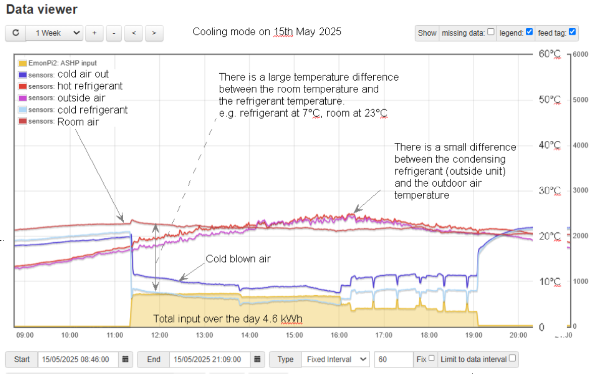
They do of course operate in cooling mode.   Whilst many will say this a good thing, I tend to think that their use in ‘cooling’ would very often be environmental laziness.  i.e. before resorting to switching on this refrigerated cooling, we should be following good housekeeping first –  shading the sun, outside shutters, inside blinds, ceiling fans etc.  If that fails…. Well, OK, turn the AC on.

The other issue here is the lack of hot water (DHW) from air-air systems.  However, the losses resulting from cylinders and pipe runs can be very considerable, and I feel that instant point-of-use electric water heating ranks better than we generally think.   I have another blog brewing on that topic.. watch this space.

So, is it a proper heating system?   It’s not a system to ‘bang in’ in every situation, but with a bit of thought, with the right controls and an informed user, it could be very proper for limited applications.


Heating Simulator

This is fantastic! I have wanted to do this sort of thing for ages, and now thanks to my niece Ellie who constructed it, it’s working!

Click here for a full screen version of the Simulator below

What is the purpose of this simulator?

What happens when we slow-down the flow rate?   What would happen if we double the radiator size?   What happens to the water temperatures and the delta if we change these things?

To get a deeper and intuitive understanding of heat, water flow rates and temperatures, you can ‘play’ with this Simulator to find out.

Fault finding has changed over the years. In many ways servicing has become more efficient. Diagnosis has become very product-specific and often done to laid-down procedures.  A downside of this is that engineers are not given the opportunity to go ‘off piste’ and learn for themselves.

Further to a teaching aid to get people thinking and talking, you could also use this as a tool to estimate how much heat your radiators could emit if working at lower (heat pump friendly) temperatures.  You just need to list out your radiator types and sizes and compare temperatures they would operate at given different heat outputs

So, there you have it.   If you wish, you can simply change the input values and see what happens.

Points to note

  • Your system configuration and controls must be set right if you are to achieve the low operating water temperatures that you are aiming for.
  • In practice, you might tend to get uneven temperatures (cool patches) with very big radiators. E.g., a 2.5 sq.m. radiator might act more like 2.2 sq.m. due to these ‘cool’ patches
  • Long rectangular radiators give out a bit more heat per than square ones.
    (say 5-10% variation??)
  • The values are good non-optimistic estimates, but check manufacturers data for more specific values.
  • The delta (difference in temperature) we are considering here is the difference between flow and return temperatures.   The same term is often used to describe the difference between room temperure and radiator temperature (e.g. dt 50°).  Don’t confuse the two.

TIPs

If you want suggestions to try… re-load the page to get default mid-range values.   Now observe the resulting water temperatures that we would see in real life.

Now try changing any one of the above and see what happens to the temperatures.

  • With more power input, the radiator gets hotter, and more heat is dissipated to the room.
  • If the radiator is bigger, it dissipates the same heat to the room, but at a lower temperature
  • When the water flow-rate reduces, the difference between the flow and return (delta, dT) increases. The flow-temperature rises and return-temperature drops. Watch the thermometers. Try increasing the heat input and also doubling the flow rate. Watch the dT.
  • If the room temperature changes, the radiator temperature changes too.  This is simply because the heat delivered depends on the difference in temperature between the radiator and the room air temperature.   So, if the water temperature is fixed, from a boiler of buffer tank, the heat emitted increases slightly if you open a window and cool the room.

Suggestion

If you have an existing radiator system, and are thinking of adding a heat pump, and are concerned about energy efficiency, then you may want to operate on a relatively low temperature to keep the heat pump efficient

  • Go to each radiator and enter the approximate area and radiator type
  • Now change the heat input (Kw) until you get an average radiator temperature of say 40°C (e.g. 42.5°C flow and 37.7° return temperatures)  (40°C = 104°F)
  • Now adjust the flow rate until the dt is about 5 degrees  (9F)
  • Note down the heat (kW) and flow rate (lit/min) for this radiator
  • Now do this for every radiator in your house
  • Total them all up

From this you have estimated how many kW’s of heat you can ‘pump’ into your radiators so that they will operate at an energy-efficient temperature for a heat pump.
(you might want to use the radiator type-in-the-numbers version)

You may of course choose to run your heat pump at warmer temperatures, and accept that your COP may not be as good.

Be mindful that some heat pumps are relatively large, so not all systems would work efficiently at such low operating temperatures, due mostly to them stopping and starting a lot.

For anyone still reading.. I thought hard about the inputs and outputs on the simulator.  i.e. should the inputs be area and temperature, giving kW output? or
should the inputs be area and kW heat, giving radiator temperature result.
I concluded that the 2nd option is a better way of thinking about it from a learning point of view.   e.g. the circulating water temperature is the final end-result of the various inputs (kWs, area etc)

Radiant temperature.  Elephant in the room?

In a cold un-heated exhibition room at the Centre for Alternative Technology many years ago, there was one of those good-for-your-posture kneeling chairs.  Surrounding this chair was a curved hardboard sheet covered with Aluminium foil. You were invited to sit, surrounded by a shiny foil surface. The effect was quite dramatic, you could instantly feel the warmth reflected back from your body.

This chimed well with claims from various underfloor heating manufacturers that for the same level of comfort, you can have a slightly lower air temperature. This is due to the radiation emitted from the floor

The theory is that every surface emits radiant heat, and this depends on the surface’s absolute temperature (e.g., no radiation at -273°C). Things absorb it too, so radiation bounces back and forwards between objects.  E.g., between you and a wall.

I experienced this when I first installed some underfloor heating in a hall in Scotland. Having finished the floor (with wooden covering) in 1 day, I slept there and assumed my thermometer was incorrect because I was comfortable in a 16°C room.  It was only later that I realised that the floor’s radiation had distorted my sense of comfort.  Not that the floor felt particularly warm, but it wasn’t cold!  This was my first experience of underfloor heating.

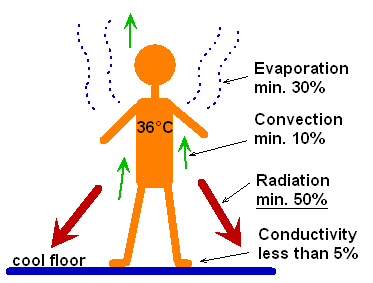
I also came across this slide about human body cooling at an energy exhibition a long time back.  I find this one hard to believe but if it is even half true, it is showing how dramatic the effect of radiation is on comfort. Cold stone floors in very hot countries certainly seem to help at midday.

‘Radiant temperature’ is a thing, and is documented in CIBSE and ASHRAE.. There is plenty to read on the topic to support the notion.  Indeed, to quote https://www.hse.gov.uk/temperature/thermal/#what_is
“Radiant temperature has a greater influence than air temperature on how we lose or gain heat to the environment”.

Why therefore is the topic almost unheard-of in general heating speak?   And why are the standard ‘comfort’ conditions suggested to be 21°C air temperature etc. with no mention of surrounding radiation?  Why are we fixated with air temperature?

This particular topic came up for me while advising on the heating at a village hall. The hall is infrequently used and un-insulated, so if they choose a quick ‘blast’ of heat from cold, the cold walls and cold floors would have a negative effect on comfort.  Occupants would radiate themselves, but get little back from the surroundings.  To compensate for the lack of radiation, and to restore comfort, the air temperature may need to be set warmer than normal. They could choose to keep the hall at a medium temperature all the time, this may add to comfort by removing (or reducing) the cold surfaces, but heating is also a continuous loss of heat to the outside.   I started to feel that I knew nothing about heating since I had no idea how to work out how much ‘discomfort’ could be caused by cold walls’, and how much warmer the air temperature needs to be, to achieve comfort in a room with low radiant heat.  I soon realised that nobody else knew either.

I got around to thinking that in constantly-heated houses, it isn’t really a problem.  The walls and surfaces might get up to around 20°C, and these all emit radiation, so there is no ‘shortfall’ of radiation.

For intermittently heated buildings, and those with stone walls and stone floors in particular, then there could at times be a considerable lack of radiation and this could lead to discomfort.

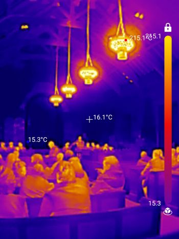
There is of course a well-established, simple and effective way of addressing this ‘shortfall’, and that is to fit infrared heaters overhead.  Indeed, they are used frequently in churches, which must be the hardest of all buildings to heat, being infrequently used and with solid cold walls and no insulation.

However, my experience of such heaters is that they are usually sized far too generously by installers wanting ‘its’s nice and toasty warm’ feedback from occupants.   But many such community buildings are on a limited budget, so maybe the design brief should be – low running cost with acceptable warmth…. you won’t find a salesman giving that pitch!

Any direct electric heating does however seem inefficient, and when comparing heat pumps with any direct electric heating, it is common to assume that any electric heater has a COP of only 1. i.e., it’s 100% efficient. 1kW in, 1kW out.  But this is not the whole story. If a small amount of electric radiant heat can mean we can drop the air temperature say 1°C, then our heat pump could have a reduced input of 10%. (i)  So, using some radiant heat only at times of occupation, or before the wall surfaces have warmed, could be a net benefit.

The more I think about it, maybe every old intermittently-heated building should have at least a small amount of radiant heat input, but finding an installer to fit a small infra-red heater might be impossible….  like asking a good chef for just one plain cheese sandwich!   And controlling it is another matter.  Turning radiation on and off is not generally comfortable.   Radiant globe sensors do exist, but you won’t easily find them.  Hopefully, as time goes on, controls will get better.

I was pondering the development and fine-tuning of heating systems.  For cars, fuel economy is so easy to measure, so there is a natural evolution towards better efficiency, but for heating, it’s extremely difficult to measure ‘comfort’ because its subjective.  The net-effectiveness of installed heating systems is hard to evaluate.  The individual products are being developed, but on the installation front, there seems to be little incentive to drive forward the little incremental improvements.  There still seems to be a long way to go, and I’m guessing that in the future will be better at gauging and correcting any shortfall in radiant heat with older buildings.

i)          https://assets.publishing.service.gov.uk/government/uploads/system/uploads/attachment_data/file/128720/6923-how-much-energy-could-be-saved-by-making-small-cha.pdf

Heat pump controls, we need better

These blogs are usually triggered when I come across issues (several times) that bother me… here goes.

Theory and practice show that the best performance for any (1) heat pump is achieved if the average water temperature that the heat pump ‘sees’ (the water temperature passing through it) is kept low (2), whilst still achieving the required level of comfort.

It is all very well installing underfloor heating or radiators that can give high heat-outputs with low circulating water temperatures.   However, the actual temperatures may deviate significantly from the theoretical, and this is highly dependent on the control system provided.  It is often assumed (by both installers and users) that the controls are capable of doing what you need… not always the case.

Whilst the SCOP rating and the predicted flow/return temperatures would seem to have the greatest bearing on energy-efficiency, it really hangs in how well it is controlled.

I am hopeful that over this decade we will see far better control systems. It strikes me that we are in a ‘middle’ phase with some claims of ‘intelligent’ control, but actually its not always helpful in practice. Furthermore, many programmers and controls are still user-unfriendly. No wonder that many are not programmed as they should be.

Whilst things have got better, I still come across installations that are clearly not ideal. E.g. inadequate controls, or sometimes too many and too complicated.  It is often very hard to estimate how worthwhile (cost-effective) any modifications would be. This would ideally involve some performance monitoring over time. So, annoyingly, many systems remain in a non-ideal state.

I don’t want to worry people unnecessarily here.  Most installers know what they are doing!  Many systems are well optimised, and do just what they say on the tin, but people still need to be mindful that it’s not always the case.

The below are some typical general examples, but there are many other offerings and options out there.

Some typical control methods

When things are simple, there are fewer potential pitfalls

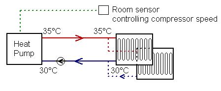
Here we have an as-simple-as-it-gets system.  In this case the room control is the ‘target temperature’ or ‘auto adapt’ type. This modulates (variable inverter) the flow temperature according to room temperature so the actual water temperatures can adjust itself from anything below 30°C to above 40°C depending on the demand.  The average water temperature over the year can be surprisingly low, giving low running costs.   In this case, the Room control is supplied with the heat pump.

This is a good system for open-plan houses, and extremely well-insulated houses, but when we get into larger houses with different rooms used at different times, and radiators upstairs with underfloor downstairs, we can start running into trouble…. To be clear… It will heat adequately, but the running costs could become higher than they should.


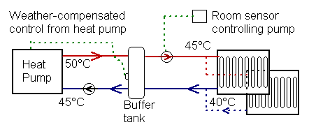
The next level of complexity may involve a buffer cylinder.  This is simply a tank of water. It might store something in the order of up to 20 minutes worth of heat.   It is generally needed in buildings where there are many zones (many rooms), and where you may at times want only one zone on.
The simple principle is this –
* The heat pump heats the buffer cylinder to a certain temperature (variable over the year).
* Heat is pumped from this cylinder to rooms as required.

Unlike the first example where the controller ‘learns’ the lowest (and most efficient) water temperature possible, in the buffer tank case, a pre-determined temperature has to be set, and this usually uses a ‘weather compensation curve’ (put simply 50°C when very cold out, 30°C when mild, and a sliding scale between the two).
The ‘curve’ setting is usually found by trial and error, but as I am all too often finding, this is often set higher than it actually needs to be. E.g. in my example it is heated to 50°C.  Water at the radiator may (due to mixing) be at 45°C, and the thermostat in the room will ‘cycle’ the pump with on and off periods.   The radiator at a constant 35°C might suffice.

Compared to our first example, the heat pump ‘sees’ water at a considerably higher temperature, so the average COP is worse.

Ideally, the set point of the buffer would not only depend on the outside temperature, but it could reduce for certain periods of the day, and also reduce depending on the house temperature.  Many manufacturers have a facility for this, but I very rarely see it being used well.   Some controls allow two curve settings over the 24hr period.  Most don’t.

Underfloor and radiators on the same system

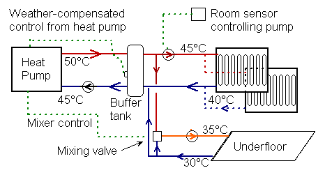
A next level of complexity is where mixing valves are used.  This is typical when both underfloor and radiators are used on one heat pump.

Here we can see an underfloor circuit that only needs water at the lukewarm temperature of 35°C.  Whilst our heat pump would heat this very efficiently, unfortunately the system takes all water up to 50° (less efficiently), only to mix some of it down to 35°C.   If our control was ‘cleverer’, it could drop the buffer set temperature for certain periods of time when only the floor needs heating. However, few currently available controls will cater for this.

These examples are only a few of many options and combinations. Of course, the manufacturers have thought this all through, however, it would be impractical to make controls for every circumstance.. it could be too complicated, so they tend to evolve a ‘system’ and hope it will suit most applications.

Intermittent and continuous heating

For houses that are unoccupied during the day, or offices that are vacated evening and night, there is no point keeping them warm all the time.  That said, if the heating is completely off for too many hours, then the required catch-up (heat-up) may be difficult for our heat pump.   In practice, a compromise is usually sought, with ‘occupied’ and ‘unoccupied’ temperatures.  This is of course dependent on the building, be it insulated or not, heavy stone or lightweight etc.

For constantly-heated homes, heat pump installations can be simpler.  But for intermittent heating, some extra complexity and extra capacity may be needed.

That said, for most of the year, there is spare capacity, so it may be perfectly acceptable in many situations to forego intermittency during the relatively brief coldest periods of the year. Again, good controls would be key to optimising this.     In the meantime, owners can set controls the best they can, but my feeling is that because programmers and controllers can be quite a chore to set correctly, many are not set well.

There seems still to be a lot to learn about the best way to operate heat pumps in different buildings with different situations, with respect to intermittency or constant.

A final gripe, .. for anyone trying to set a digital room thermostat to a frugal setting.  This could be in a workroom of maybe a big lofty room in an old house.  The ‘jump’ between settings of 16°, 17° or 18°C is great.  If energy-use is a minor issue, then you simply go 1° higher, but if you are keeping a tight rein on cost (e.g. a village hall), a finer control is desirable.    Manufacturers… please allow ½°C adjustment increments.  (It seems that 1°F increments are however about right). Gripe over.


Footnotes

  • (1)  The exception here could be a ‘transcritical’ heat pump using Refrigerant R744 CO2. These produce very hot water with relative efficiency, but don’t generally achieve the high COPs at low temperatures that other conventional types can.
  • (2)   How low can you go and still get an increase in COP? Whilst graphs show a trend of increased COP down to say 30°C, what happens below this?  I have done various ad-hoc test to the best I can, and found that some older fixed-speed designs tend to flatten off around 25-30°C.  But I have been surprised how efficient some inverter units work. This is could be to do with two things. i) better refrigerant control with an electronic expansion valve and ii) better motor power at very light loading.


Heating old buildings with heat pumps


Also see YouTube here                                     (index of other blogs)

It’s great to see how heat pumps are becoming mainstream, and increasingly the norm for newbuild.  However, I have noticed ongoing confusion relating to the use of heat pumps in old buildings.  The confusion can start with the ‘will it work’ question.  Let’s be clear – the right heat pump could be made to heat any building to any temperature we like. But the crux of the issue is the installation cost and the running cost.  The question that we should ask is – ‘can we heat old buildings and achieve acceptable energy-efficiency?’  Well… we probably can, and as time passes, it gets better.  Let’s drill into this.

On one level, it is quite simple, but on another level quite complicated.

The simple level relates mainly to the circulating heated water temperature required for poorly-insulated buildings, and this directly affects the energy-efficiency; the Coefficient of Performance (COP) – what heat you get out compared to what electricity you put in.  This has implications for the environment and also for running costs.

The complicated level relates to where you want the heat and at what times, and this is all wrapped up with the type of building and its use….   Does it have a lot of internal ‘mass’, brick walls etc i.e. is it slow to heat, and thereafter- slow to cool down.  Or is it ‘lightweight’ and mostly insulated internally – quick to heat and quick to cool.   Add to this is the occupancy; is it occupied all the time, or empty during the day?    Then there are off-peak tariffs and possible future ‘smart grid’ to consider.

Don’t put your hopes too high on finding definite answers here on how best to deploy heat pumps on old buildings for all situations, but you may glean something about where and how heat pumps are likely to be most worthwhile, and also where a good grasp of control settings may be needed.

Heat pumps can promise a fit-and-forget technology, but they sometimes need a modicum of user-engagement if the best results are to be achieved. Maybe more-so in poorly insulated buildings.

The easy stuff

As everyone should know by now, heat pumps are very efficient at producing lukewarm water – It’s an easy ride for them.  However, as the water gets hotter, the electrical power-input requirements rise too – the energy-efficiency drops and running cost rises.

The obvious solution to this is to use large-area radiators or well-designed underfloor heating. Both can often provide adequate heat with water temperatures well below ‘hot’.  (say 30 to 40°C,  85-105°F) for much of the winter.

Here is the nub of the issue relating to old buildings – it’s more difficult (and a more costly installation) to design a heat-emitter system (radiators or underfloor) to adequately heat an un-insulated building. Especially if using the low water temperatures that energy-efficient heat pumps require.  By contrast, well-insulated buildings require far less heat, so should not require overly large radiators. They are the ‘low-hanging fruit’ for heat pumps.

Conventional heating has generally been designed with high-output, for short periods.  From plumbers to householders, we are all used to ‘turning the heating on’ and feeling warm fairly quickly.  However, heat pumps are far happier operating with lower water temperatures, and this is where some confusion can start. Some patience, and also some confidence in the system is required when setting the required low water temperatures. This is because the system will respond very slowly, and you need to plan ahead and let the building to warm up gently. We are now erring towards a more continuously-enabled system, and contrary to instincts, a heat pump system operated like this can use less energy than one operated on an on/off time clock.

Intermittent heating / constant heating…… starting to get complicated

If the heating is required at a constant temperature, e.g. a retirement home, then things are very easy. The radiators may be able to operate ‘warm’ (not hot) all the time, resulting in very high energy-efficiency (high COP).

Keeping your house warm when you are out is generally seen as wasteful… why heat when you are not there?   However, if you do operate with a timer, and allow the house to cool down during the daytime or overnight, then you will need to operate the radiators at an elevated temperature so as to ‘catch-up’, and get the rooms back to a comfortable temperature.   The COP will be lower at this time, so you get less heat for your money whist operating ‘timed’.   But if timed, you need less total heat due to the lower average temperature of the house.   That said, heat is stored in the building’s fabric, so heating while you are out at work is not as wasteful as you may first think.

Both factors (on-all-the-time low, or intermittent and high) can tend to balance out. What you gain on one, you can lose on the other, and vice-versa.   The best efficiency is likely to be found with far longer run times than we are traditionally used to.    Instead of starting heating 1.5 hours before you get up, try 3 or even as much as 5 hours before, but adjust the circulating water temperature down first (or reduce the heating curve).

The thermal ‘weight’ (or mass) of the building will have a big impact here.    If the building is an old brick house (heavy), and a set-back (reduced) temperature is programmed for the night or un-occupied day, then the radiators may need to be considerably warmer to provide comfort in the evenings – not helped by the cold walls.   So, in this instance, like the race of the tortoise and the hare, the on-all-the-time tortoise can have the edge due to the good COP resulting from the constantly-enabled lukewarm radiators.

On the other hand, if the building has a lot of internal insulation, and few stone/brick inner walls, it will be thermally ‘light’. In this case the ‘catch-up’ to re-heat to a comfortable temperature should be acceptably short, so an amount of night set-back (lower room temperature at night). is likely to be advantageous.

Unfortunately, I don’t have data or evidence to say where the lines should be drawn, but have in the past been surprised how cheap to run some constantly-enabled heat pumps can be.

A word of warning here. Not all system configurations are that easy to ‘optimise’ for maximum energy-efficiency. The aim is to achieve a low operating water-temperatures and still get adequate heating to the building. If you have a weather-compensation heating-curve, the setting will need engaging with, and hopefully reducing. This should be easy to do, and don’t forget that the response time may be slow.    Be mindful that simply reducing TRV radiator valves is not addressing the issue here since the heat pump is not ‘seeing’ the lower water temperature that it likes.

The lowest running costs are likely to be achieved with some amount of night set-back.  However, it can be easier, with less risk of setting something wrong, to set the system to constant. You can then find the lowest circulating water temperatures that still keeps you adequately warm.  It can be worth experiment.   Try it and note down daily electricity use.

The bigger picture

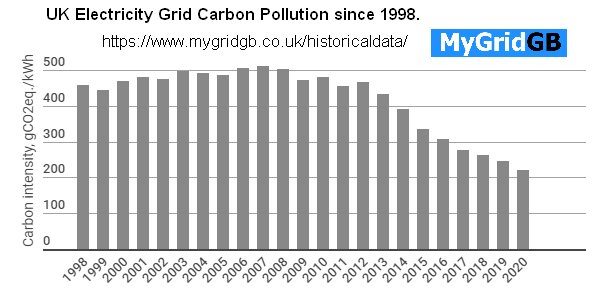
The goal posts in the UK have changed greatly over the last 10 years (say 2010 to 2020).  Electricity generation is now twice as ‘green’ and beyond my expectations.

The increase in solar and wind generation, coupled with the phasing down of coal and advent of efficient gas power stations has resulted in the CO2 pollution halving in 10 years.   This means that lower COP heat pumps are more acceptable.   Added to this, heat pumps have bit-by-bit become more energy-efficient.  All-in-all, with a far better selection of energy-efficient products in a now well-established industry, we are far better positioned to install heat pump in all types of building.

Furthermore, there could also some positive advantages for using heat pumps with old ‘heavy’ buildings.  The storage of heat in the building’s fabric can mean that we could partly ‘shift’ (in time) the running of the heat pump to coincide with available PV solar, or to benefit from different time tariffs.  Future Smart Grids may, in a small way, use the slow-response of old buildings to advantage.  We could also ‘incentivise’ and air source system to run at the warmest time of day when its efficiency is high.   We are not quite there yet with the necessary ‘intelligent’ controls’ to be able us to control as in these ideas, but it’s coming.  I look forward to seeing developments in this area.

mygrid.com UK grid carbon CO2 history
MyGrid.co.uk Trend of UK CO2 from generation

HOME


Kilowatts per hour! A guide for the perplexed.

There is a little detail that annoys many people.  It’s the confusion that seems to arise over the commonly used units of energy and power

I came across this the other day and pondered why it’s a common error.  When we drill into the details, we can see why confusion could arise.

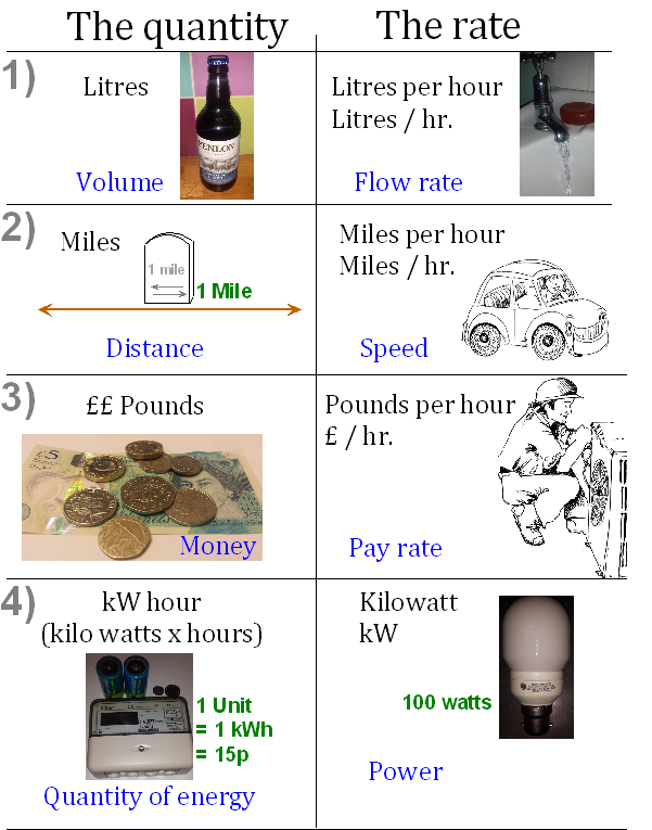
We are all used to lots of things that are – ‘per hour’   e.g.   Speed in miles per hour, water flow-rate in Litres per hour, wages in Pounds (££) per hour.

The unit of energy –   kwh, is the odd one out.  There is no ‘per’ involved.  We will come back to that in a minute.

If you think about it historically; miles, litres and money came well before any thought of needing the ‘per hour’ rate of these things.    E.g. We measured Miles well before we thought of needing a unit for speed…. Miles per hour.

Apart from in science circles (who got it right of course), I would think that the units of power and energy evolved historically the other way around.  The first unit required was power – the horsepower, the watt, or the kilowatt.  When we first started generating electrical power, it was horse-power or Kwatts that was the all-important unit.  E.g Watts as a measure of the intensity of a light bulb etc.

The next consideration would have been measuring the total quantity of power over time.  If we generate 1kW of power, then after 1 hr, we have a quantity of energy of 1 kW multiplied by 1 hour.   In a whole day, we would have 24 kWhrs (kW x Hrs), or 24 units of electricity.  Now a utility bill can be sent!!

The image below illustrates various examples of quantities of something on the left, with the corresponding rate to the right.

The first 3 above are easy to understand, but the last one is a little strange.     Given the common unit for power was the kWatt (on the right), then to find a unit of quantity we need to multiply power by time, not divide by time as for other units.

One important point to mention, that some people miss, is the  ‘/’. This means ‘divided by’ or ‘per’.    However if we want a ‘multiply by’ in our units,   what do we put??   We put NOTHING!   How confusing is that!

e.g.       Miles per hour or miles divided by hours   =    miles  /   hr.
Kilowatts multiplied by time                   =      kW         hr.
That gap in between the kW and h means ‘multiply-by’  !     I know its so obvious to scientists, but if we actually put something in the gap it might make it more understandable.  E.g. if we said ‘kW hrs’, but wrote kW.hrs,

Maybe it’s no wonder that there is confusion.

So here is how to never get it wrong again.

kWatt  is the amount of Power.
A 40kW car engine, a 2kW kettle, a 50W light bulb

kWatt hr.  is a quantity of energy.
One kWh is one unit of electricity and costs about 15 pence.  A typical household may use 5,000 kWh of electricity over a year. (costing £750)

kWatt/hr. is unheard-of

Distributing hot water to tap outlets

To my mind, the whole point of having a heat pump is to save energy, so it somewhat jars with me when I see one aspect of a system that is not in-line with that aim.

A heat pump always stores Domestic Hot Water (DHW) in a cylinder. The Cylinder is, we hope, sized and optimised for heat pump use so that the COP (and lowest running cost) is the best-we-can-get.  This detail should be taken care of by the manufacturers and designers.

The detail of distributing the water to the taps is however often done using rule-of-thumb and the installer’s past experience.  Energy-efficiency is often low down on the priority list, so may be given little thought.

Hot water must of course be available at a sufficiently high flow-rate, this may lead to choosing a large-bore supply pipe.   However, this large bore pipe holds a lot of water, so when a tap is turned on, there can be a long wait before the tap runs hot.  After the tap is turned off, the heat from this volume of hot water left in the pipe is slowly lost.  This is not good for energy-efficiency and low running costs.  This may in-part usefully heat the house, but often it is simply a waste.   It is certainly a waste of water.    I recently came across a pipe run that took such a long torturous long route that I filled a whole sink before the tap stared to run warm!

For sake of energy-efficiency, the distributions to taps should be;

  1. The smallest diameter to give adequate flow rate
  2. As short as possible – the most direct route.

Normally, a single ‘main artery’ is taken from the cylinder, and run to taps in turn. This distribution pipe will normally start big and, as each ‘tee’ off to a tap, it will at some point reduce in diameter. Furthermore, if several taps are on at the same time, then one flow may affect the other. E.g. the pipe needs to be big enough in diameter to maintain a good steady flow-rate for a shower.

The choice of pipe size is often a dilemma, so playing-safe and choosing larger pipes would at least safeguard against an inadequate pipe run. This would however tend to go against saving energy.

Running separate pipes from the cylinder.

The pipe run to the bath is usually large diameter. This is where the fastest flow may be needed so that the bath fills quickly. However, a bath is not used very frequently, so the losses as described above may not be as great here as envisaged.   Kitchen sinks however tend to be used many times over the day, so total losses of heat and water could be high.

The worst scenario could be a kitchen sink at the end of a large long pipe run via a bath.

A solution to this could be to run dedicated pipes directly to sinks.

Here are some suggestions for new-builds

  1. Position the cylinder as close to the taps that are most frequently used (e.g. the kitchen sink). Ideally find a central location to all taps.
  2. Early on in the build, organise the most direct pipe run routes from the top of the cylinder to the sinks.   (the ceiling is often shorter than running in the floor)
  3. Decide the best configuration, e.g. some sinks can share, others may benefit from their own dedicated supply pipe.
  4. Identify the most suitable diameter of pipe.
  5. Insulate frequently-used pipes, BUT this may give limited advantage since it may simply take longer to lose all the heat in the pipe.

Pumped secondary return loop

Hotels and large houses often adopted a pumped circulation loop so that the taps run hot almost immediately.  This saves water and is convenient to use, however, the hot loop can waste a lot of energy, even if well-insulated.  I would try to avoid a pumped loop if possible.  It may be better to have point-of-use direct electric heaters, than to have a pumped loop that is always wasting heat.

Copper v plastic

There is a bit of a myth that suggests that plastic pipe is ‘smoother’ than copper.  The most important factor for flow-rate is the actual bore size. The wall material makes little difference.  However, plastic can very easily be bent with sweeps, these are better than straight pipes with tight bends. In this sense, plastic can be ‘smoother’.

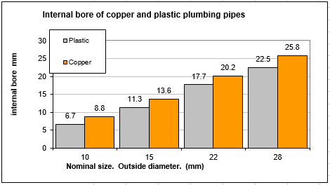
Anyhow, the difference between copper and plastic is quite dramatic due to its internal bore.

It is very important to allow for the internal pipe sizes, and it is possible to use a combination of the two, e.g. run plastic through the middle of joists if it’s possible, but use long straight runs of copper along a wall.

I have put two charts at the bottom of the page here    http://heatpumps.co.uk/types-of-heat-pump/domestic-hot-water-dhw/

There are figures here to give a rough idea of what sizes might work.  It is surprising how much more restrictive 15mm plastic is compared to 15mm copper.  This info goes along with a disclaimer since it can be hard to know all the factors involved in a system.  I am a great believer in getting a sample of pipe in a coil and doing a test on site with a bucket.

You can also play with this great little pressure-drop calculator   for theoretical pipe sizes

What could go wrong?

I have successfully run a kitchen sink via a 10mm plastic pipe.  The bore is only 6.7mm which is less than the diameter of a pencil.  I had no noise problem at all.   In general, more noise would come from part-open valve or tap than would come from a smooth pipe.   Remember to clip the pipe well to stop any annoying clonking that can occur with any pipe when a tap is shut-off quickly.

Pressure drops, flow-rates and LENGTH

(Note- if you are reading this.. you might also be interested in my new flow and pressure simulator)

What is the point of having a large diameter pipe run when the fittings on the heat pump are small?

I have heard that statement enough times to make me want to write a blog about it.  

It seems intuitive to think that any bottle neck in a pipe system is the limiting factor for the flowrate. At first thought, it seems like the ‘weakest link’ in the system.  I then started to wonder why this topic is so well understood by electricians and so misunderstood by some plumbers.

I also recall chatting to a Heating College lecturer who said “They have made these training courses so you don’t need to think anymore”. If that is the case no wonder the topic can be perplexing. However, it is far from rocket science.

So a little thinking …

For water to flow through a pipe system, a pressure difference is required. [between (A) and (C)]. This pressure is usually provided by a circulation pump that literally pushes the water through.

The flow-rate depends on two things, 1) the pressure difference between (A) and (C), and 2) the total restriction of the pipe.

Electrical circuits are almost the same.

In electrical terms, we have Voltage (the pressure), current[amps] (the flow-rate), and total resistance[ohms] (the restriction of pipe circuit)

Every electrician knows Ohms law intuitively –

v = i multiplied by     or             volt difference = amps x resistance[ohms].

However, heating does not have a commonly known equivalent
e.g. pressure difference = flow-rate x restriction

The reason why electricians have it so sussed is that they have the tools to know exactly what is going on in every circuit. A volt meter can show the voltages at all points in a circuit. A current clamp can show the amps that are flowing. We can easily know exactly what is going on in any cable.(e.g the voltages at points A,B & C)

Plumbers have no such luxury. We would need tapping ports at various points around a circuit if we want to know pressure differences.  We only know the static pressure at one point, which tells us nothing. Furthermore, we generally have no idea how much is flowing in each individual pipe run. There is also no easy way of measuring the resistance of a pipe system, so there is no easy resistance equivalent for pipes and fittings. All-in-all, the heating engineer is very much in the dark, and would have little idea what the pressure is at point (B).

Now let’s consider a simplified scenario that an electrician might face –

Here we have a PV panel at a long distance from a house. It will make perfect sense to any electrician to have a very thick long cable from (A) to (B), whilst having relatively thin cables at each end. The important requirement here is that the total volt-drop due to total cable resistance is kept low. For every metre of cable, there is a very small volt drop, and all these add together. The calculations can easily show the volt-drop. You can use a cable calculator on-line.

It is the LENGTH here that is the issue. If (A) and (B) are close, that section could be thin, but if the cable is long, it need to be fat. If the cable is very long, it needs to be very fat. However, making the short ends any fatter will make very little difference to the total volt drop.

Back to our water pipes,

The same thing applies. Every metre of pipe causes a pressure drop (when water is flowing), and every metre adds up. Again, it is the LENGTH that is a major issue here. For example, if you have say a 5m length of pipe and you need 1m head of water (0.1 bar) to make a certain flow rate, then you need twice the pressure if you have twice the length. 50M of pipe would need 10m head (1 bar) to give you the same flow rate. However, it you swap that 50m long pipe for one of bigger diameter, you will have far less ‘resistance’ in the pipe. The required flow rate can be achieved with far less pressure.

You can play with an on-line calculator to see what happens with different pipe sizes and lengths. See http://www.pressure-drop.com/Online-Calculator/

It is easy to overlook the pipe LENGTH, this has just as much affect on the flow and pressure drop as the diameter does. This is why a water meter with a very small bore does not affect the flow-rate very much – it is very short. Put 10 water meters in-line, one after another, and you have a big restriction, and a big problem.

So, back to our earlier assertion that any small-bore section of pipe bottleneck is akin to the weakest link;       The bottle-neck principle does not apply here in the same was as it would to traffic on a motorway. If cars acted like water molecules or like electrons, they would push bumper to bumper and shoot through a bottle-neck at extremely high speed!

I have added a page on this topic here http://heatpumps.co.uk/technical/pressure-drops-flow-rates/

An example

To finish, let’s do a little exercise on pipe sizing. Let’s look at a scenario with a 10m (30ft) high header tank is supplying a tap/valve via a large bore pipe. i.e. a good 1 bar pressure supply of water. Let’s consider extending this pipe horizontally and look at what flow-rate will emerge out the end of it. We are assuming 1 bar pressure at the start, and zero bar (atmospheric pressure) at the outlet.

We can firstly consider a 15mm (outside diameter) pipe (the most common pipe size for taps).
One 40m length of this plastic pipe would give us a flow rate of around 8litres/minute (About 2.1 US gallons/min or 1.75 UK gal/min.). This is a typical bath-tap flow rate.

If we use copper instead, the wall-thickness is thinner and internal bore is bigger. We could have well over twice the length of pipe and get a similar flow rate coming out of the end.

As you can see from the grid, you could go as far as 720m if a 22mm copper pipe were chosen.

If we go in the other direction and fit a small pipe, we can see that a 10mm copper micro-bore pipe that was about 14m long would still give us 8lit/min. If we now look at 10mm plastic with its small internal bore of only 6.6mm (pencils are fatter than that) then it could be no longer than 3m if we want the same flow rate to fill a bath.

This simply illustrates how the diameter and length could be adjusted to give the required flow rate given a certain available pressure.     In summary, a short thin pipe may act similarly to a long fat one.